openenergymonitor's Energy Monitor (Pete's Portable, Current Only Version)
Last Revised: October 22, 2023
Home Computing
My Arduino Startup Page Contact Us
Thanks again, to my friend George Adams for bringing something fun and useful to our recent
Arduino meeting.
Why bother? Why not just go to the openenergy website and buy or build your own complete unit?
Answer: Because the complete unit requires both a Current Transformer and a Voltage transformer, which makes it less than portable or easy to simply
"Clamp On" to the wire to be tested.
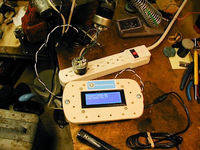
This one is battery powered and only requires a small CT that clips around the wire of interest. Besides, it's fun to do.
I built my own "Energy Monitor" on about February 2, 2018.
It measures only the current flow in a single conductor of a 120 volt ac circuit, using a cheap Current Transformer.
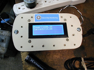
This version (my code) reads out the current directly, but simply calculates
wattage by the formula: Watts (Power) = Amps X 120.
You can change the "120" within the code to be whatever nominal voltage the circuit to be tested runs at.
I used one of the CR Magnetics 3110-3000 Split-Core Current Transformers.
It has 3100 turns as opposed to the 2000 turn type which is used in the original plans.
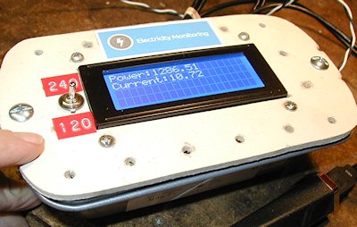
The original arduino version only outputs to the serial monitor, but we added an I2C LCD.
You see a 4 line LCD in the picture, but you only need one with two lines.
The code that I ended up with is:
Pete's Emon code
Note that you will have to go to the links above to get the "emon" code package which includes the emon library (which does most of the work).
In fact, that library does so much of the work that I found it difficult to see how the program actually works. But that's just me.
I assume that you already have the "LiquidCrystal_I2C.h" library within your IDE, too.
My version is built into a small metal cake pan with a pegboard masonite top cover which holds the I2C LCD. I think I used 6-32 screws and nuts for that.
It is based on a Yourduino Robored UNO clone.
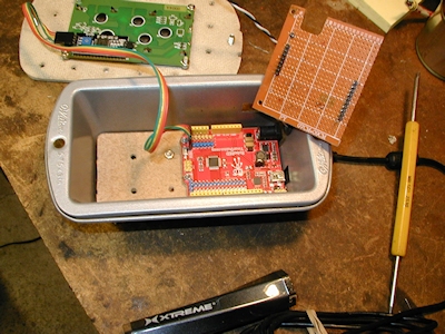
I screwed the UNO to a piece of masonite that fits snuggly into the bottom of the pan. This base holds the UNO down and insures electrical isolation.
Note: 3-48 screws and nuts work well for this. 4-40 screws would go through the mounting holes, but the nuts would interfere
with the headers in a couple of locations.
Then I screwed that masonite to the bottom of the cake pan with one screw.
To get rid of the breadboard that I had used on my test setup, I made a proto shield from a piece of "Grid Style"
Radio Shack PC board material.
I had to cut out a notch in one end of the board to make room for the Robored's I2C connector.
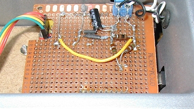
Yes, I know I am soldering on the same side of the board that the components are on. For simple circuits it is easier to see
everything from one side of the board.
Note:
Having only the individual copper pads makes circuit assembly messy.
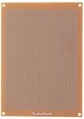
I won't buy any of that style PC board material again.
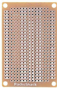
This style would be better, since it has at least SOME pads with connecting traces:
Also, as we know, the Arduino doesn't have standard .1 inch pin spacing throughout.
Each individual connector does have that spacing,
but the spacing between connectors, like between D7 and D8 and between A0 and Vin are not at that pitch. However,
I was able to make the piece of grid style board work by carefully placing header pins and by slightly making the headers "lean over" a bit.
Note:
I looked around a lot to try to find a shield or proto shield board that made room for that robored connector, but no luck.
I couldn't even find one where I could cut out that part of the board where the connector would fit.
I have finally decided that, I will just get some proto shields that DO have some combined traces, not just all individual holes.
That will make it easier to build on.
And, to accommodate the I2C connector on the Robored, I will simply bend the 4 pins on its board to 90 degrees to enable the connection.
------------------------------------
Revision One, Already!
* This change adds an SPST toggle switch to the cover and some code to tell the system to calculate watts (Power) using
* a user selectable voltage value of either 120 or 240.
* This method works because the circuit itself doesn't care what ac voltage the CT is clamped around, as long as we know what it is.
* See, we can get a fairly accurate current reading in either case, but it would be nice to
* have the "Power" reading on the LCD be close to accurate.
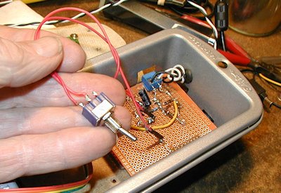
* I mounted my little switch (only needs a 15/64" diameter hole) to the top of my project box, just to the left of the LCD.
* Note: I don't print the active voltage setting to the LCD because the code is set up for a 2 line LCD.
* I am actually using a 20 X 4 LCD, so I could do that. But, I suggest physically labelling the switch so there's no
* doubt which setting is being used in the power calculation. (That's what I did).
* Connections: One lead of the SPST switch is connected from to +5 volts. Its other end is connected the to junction of D8 and one
* end of a 10K ohm resistor. Other end of 10K resistor goes to ground.
* Lastly, we are assuming a totally resistive load when taking the power reading (P=EI).
Link to the software for this version
------------------------------------
From the openenergy.org website:
Burden Resistor Notes by Pete:
The website's plans call for a 33 ohm burden resistor across the CT leads (using their 2000 turn CT).
I originally used 2 ea. 15 ohm resistors in series. They measured 31.1 ohms.
With no current flowing in the CT, I saw about 0.26 amps on the LCD readout and about 31 watts. That's not too bad, but I thought
I'd do some trimming of that value to get the "idle current" reading even lower. So. after a few calculations and then some tests,
I ended up by paralelling the 31.1 ohm resistor with 100 ohms.
That got me down from the 260 milliamps to about 20 milliamps at "idle".
I have tested the output at 3 different power levels, 150 watts, 1300 watts and 1650 watts.
The current and power readings are all pretty close, so I won't mess with the low end any more.