JXQ-10A, Update to Setting One Up
Updates to my knowledge of the JXQ-10A Gasifier since I put the main page up:
Last Revised: October 22, 2023
French Creek Valley Home Back to Our JXQ-10A Main Page
Contact Us
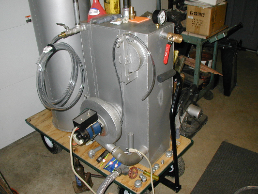
After input from some of you on the Gasifier list, I decided to add a cyclone separator to try to get extra tar and
condensate out of the gas stream. So I built an exact copy of the GEK cyclone separator. I have now attached all the
plumbing I need in order to fire the thing up. I added a flare. I added an output pressure gage just behind the flare
and a +/-12"WC differential U-tube manometer to sense differences in pressure between the middle and right hand chambers.
For the first firing, I will hook it up to the stove that came with it. I don't get my generator set until the end of
this month.
Ready to Go
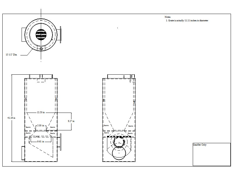
CAD Drawing of What I think is inside the Reactor
What's in the Filter Box
I'm now ready to declare what I think is actually inside the filter box. After much poking around, measuring around
corners, etc., I drew up a CAD image and I will present it below. Now that I have the machine ready to fire up, I have
been able fill the lower chamber with water, to the prescribed level, and run the blower. I have watched the pressures
as I did various things to restrict the input and output as might occur during realtime operation. These tests seem to
confirm that I'm on the right track.
Please feel free to correct me if you find an error.
There are 3 "tanks".
The left approximately 1/3 of the filter contains the cooling water tank. That is a separate tank and holds cooling
water. I suppose that if you are only using a tiny bit of gas, you may not need to constantly run cooling through it.
As we received this machine, there were quarter turn valves on both the upper and lower pipe connections, but there was
an open top tee on between the outlet pipe and the valve at the top. I assume that one can fill this tank by pushing
water in from the bottom until it runs out the top of this tee. Then one could leave the tee open so as the water
heats up, it has someplace to expand to.
If you will be using lots of gas, then I assume you will need to keep up some sort of water flow to keep the water
temperature down. Cool gas is dense gas. I will attach a garden hose to the lower tank pipe and push cool water in there.
I will plug the upper tee so the water will have to exit through the valve at the top to a drain hose.
The center tank contains the blower's suction side. The right hand tank contains 3 baffles and, at the top of this tank, the "final filter" chamber. These two chambers are separated by a metal plate the extends from the top of the filter to within about 2 or 3 inches of the bottom. Water that is poured into the right hand tank through the vertical stand pipe fills both chambers. The little 1/2" diameter tube welded to the side of the standpipe is located at about the maximum level that the is to be filled to, I think.
CAD Drawings of What I think is inside the filter box -The hot gas comes in from the left and is directed downward through a perforated plate and into the water by the
90 degree elbow.
-On the way through the incoming pipe and elbow, the hot gases loose some of their energy.
-As the blower suction pulls the gases down through the water, dust and some impurities are caught and removed from the
gas stream. More gas cooling also occurs. One might be lead to believe that some of this heat is transfered to the left
tank by conduction through the common tank wall.
This process must cause a lot of bubbling and frothing. This bubbles must be prevented from
getting any further, so:
-The blower's input pipe has a 90 degree elbow pointing upward and that upward pipe is almost 12 iches long.
Since the blower's input is about 2 feet above the water at this point, I assume that hardly any of the bubbles or
froth reach its input.
-The blower pushes the now cooler, cleaner gas back into the water that is in the bottom of the filter, but this
time, it goes into the water filled space in the right hand tank. The gas has to bubble through the water again.
-Now the gas is forced upwards and it encounters 3 horizontal baffle plates that force the gases to change direction 3
times on their way to the final filter. I assume this process removes some water and maybe any heavy particles that
somehow made it this far.
-The cooled and fairly impurity free, but not tar free gas now pushes upward through the perforated plate that is the
floor of the final filter chamber. The manual says to fill this chamber with "maize cores" (corn cobs) or with
activated charcoal. I am worried that little bits of this material might fall through the 1/2" holes in the
perforated plate and later plug the drain, so I will cover the plate with metal window screen. Anyway, we will use
charcoal that we think is "activated" because we have been told that charcoal can trap tar, whereas corn cobs can not.
-Finally, the gas exits the filter at the top of the right hand chamber.
-That's not the end of the story, however.
What about the little 1/2" pipe welded to the side of the standpipe?
The manual says to connect a rubber tube to the 1/2" diameter tube and to hold it above the outlet when the gasifier is
running. Well, if you fill the lower water tank to about 4" in depth, that's just about the same level as the bottom
of that tube. The manual says that you should lower the tube to drain the excess at the end of the run.
I guess the idea here is that any additional condensates will add to the depth of the water in the tank.
I also guess that they think the "bad" stuff will accumulate on the surface of the water in there,
so letting the excess out will get rid of the bad stuff that the system has collected during the run.
What about the standpipe? The standpipe is the only way you can get water into the lower tank.
In the original patent drawings, which, as you know are very different from what we have here, show a funnel sitting on
that pipe. Maybe not a bad idea, but I have put a small fishing bobber in there so I can see the water level in the
right side tank change as the blower's suction dynamics are at work. The fact that the standpipe is open to the
atmosphere leads me to believe that it's a sort of an air lock/safety valve/regulator, a potentially messy one, at that.