1000 Watt ZVS Induction Heater Notes
Created: November 24, 2016
Last Revised: October 17, 2023
Home
1800-2500 Watt ZVS Induction Heater Page
Work Coils
How to Make a Complete Basic System
Adding a Frequency Counter
Computing
Blacksmithing
Contact Us
Start Here
---Or--- Continue on down this page to see how I got started and where I have been going:
Download the spreadsheet below for:
-A list, with links, to all of my ZVS Induction Heater Videos,
-A list, with links, of most of my related ZVS Induction Heater Webpages,
-And My ZVS Induction Heater FAQ:
ZVS Induction Heater Video Links,Web Page Links and FAQ
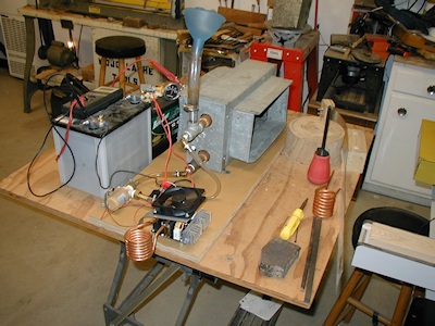

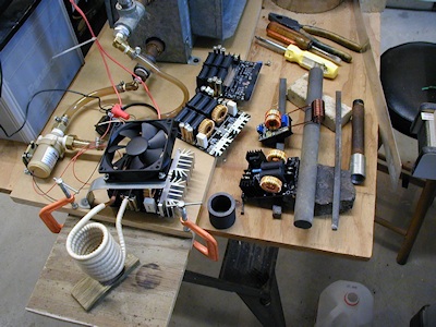
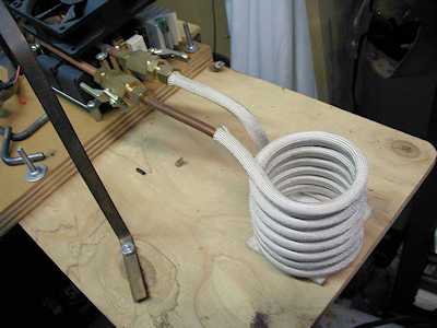
#3 1000 W ZVS Induction Heater Setup Just before I destroyed it #4 Setup, ready to test for the first time
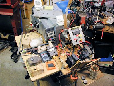
#5A Setup, 48 Volt 26 amp Power Supply with many other upgrades
Note the 12 Turn Work Coil, additional set of 6 Capacitors and second Cooling Fan. This version runs at about 43 KHz
My ZVS Induction Heater Videos
This is a page in progress!!

This is my best approximation of the schematic for the popular 12 - 48 VDC 1000 Watt ZVS Induction Heater
(currently being sold on Ebay and Amazon). This is the one that has 6 each, 0.33 mfd capacitors.
Some of the notes are from the original author. Although I have thoroughly traced out this circuit,
I take no responsibility for the accuracy of this drawing.
You must verify it for yourself.
Here are the main points that I want to cover:
1. The glowing workpiece that you see in the work coil on the youtube videos ALWAYS looks brighter on the video than it does to the human eye.
2. Somebody needs to unravel the "Chinglish" instructions that I find on a couple of the websites that sell them.
3. You can't really heat steel well enough to do any real forging because of the reduction of internal "friction" to the varying magnetic
field in ferrous metals
as the steel reaches its transformation temperature (which in the range of about 1450 to about 1550 degrees fahrenheit, for plain carbon steel).
The steel just doesn't get much hotter than that.
4. So, why doesn't the steel get hot enough? That's because the frequency of the circuits that are sold as "1000 Watt ZVS Induction Heaters"
with about 2 (6 X .33) mfd of capacitance have a tank circuit oscillation frequency of about 100 K Hertz. I think you need to be down in the 30 K Hertz range
with the power that this device has to get steel parts as hot as possible.
5.Why it breaks, What breaks, and How to Fix It
6. Operation and Testing- This is my continual "RUN LOG"
1. The Glowing Color
I ain't no expert, but it appears to me that hand camera and camcorder CCD arrays (the camera's picture sensors) aren't color balanced with hot steel in mind.
I have taken
many pictures and have produced many amatuer videos of "hot iron" and the iron ALWAYS glows brighter in the picture than it does in reality.
If you watch a few videos of these induction heaters (the 1000 Watt, $30+ dollar kind) you can often see that steel in the coil glowing so brightly that
it looks to be a high yellow color (about 2000 degrees F) or even white (about 2300 to 2500 degrees F). In actuality, a piece of steel that hot would
be sparking vigorously as it prepares to melt.
The highest actual COLOR that I have seen using 3 different examples of this heater is what I'd call a "medium red" (about 1400 degrees F).
Have you seen a couple of videos where the guy takes the temperature of the steel? Have you ever seen a reading much over 800 degrees C (or about 1500 degrees F)?
2. Chinglish Instructions
I don't mean to sound derogatory by using this term, but it IS fitting since it deals with the language and cultural differences between the English language and
the Chinese language. Maybe, when the Chinese technical writers tranlate into other languages, these problems don't exist, but they sure create problems here,
for me.
Here's my ongoing attempt to do some unravelling:
Unravelling ZVS 1000 Watt Heater Chinglish
There may be some duplication of this page within that document, but I hope you will find most of it useful.
If you see anything here or there that doesn't make sense to you, or if you see something that you feel is downright wrong, please let me know.
3. Steel's temperature stops increasing
It's the resistance to the magnetic oscillations that causes molecules to rub against eachother and thereby heat up the part.
With magnetic materials like iron and nickel, the little magnetic "dipoles" have to constantly switch direction and that adds to the "friction" AS LONG AS THE
MATERIAL IS MAGNETIC!
But, when the steel gets hot enough to undergo physical changes at its transformation temperature (WHERE IT BECOMES NON-MAGNETIC),
the material's structure changes to one that
doesn't resist the magnetic fields as much, so the part reaches an equilibrium temperature and pretty much stays there.
Just to give you an idea of how much power you can expect from this device:
If you could use ALL of the power (1000 Watts) in this induction heater to actually heat the workpiece, you would be getting 3,400 BTU of heat.
But, due to circuit power losses, only about 80% of that power gets to the work. So then you have about (3,400 X .8)= 2,720 BTU left for heating.
Just for comparison, the BTU output from gas powered kitchen stove burners vsries from about 5,000 BTU to about 25,000 BTU, with the average being
about 9,500 BTU.
4. Frequency Too High
Commercial units run at frequecies well below the 100 K Hertz that this one does. I don't know why no one else has already commented on this issue.
One experiment that I plan to run is to use the capacitors from one of my failed boards in parallel with a those of a working unit.
I will also make a work coil with twice as many turns.
I think this will reduce the frequency by a factor of two.
If it does work that way, I should be able to get my steel to a much higher temperature.
if THAT works, then I'll try adding a third set of L and C components.
Another frequency-related point the no one has mentioned yet:
Copper doesn't seem to heat up at all with this unit as it is. Yet the general info on the subject seems to imply that "anything that conducts electricity"
can be induction heated.
I have just received my first graphite crucible. I assume that its characteristics are more condusive to induction heating with this device than some non-ferrous
metals.
I think we all have seen solder and aluminum (sorta) being melted in those graphite crucibles. At this point, it's my assumption the the induction heater
heats the crucible wall and that heat is conducted to the metal within.
We will see.
5.1. Why it breaks, what breaks, and how to fix it
If you want to skip this part and get right to repairing the board, I have just now (Feb 2, 2017) added a troubleshooting guide.
Before I even get started here, I strongly suggest that you don't even start to play with this thing unless you have a fairly accurate 0 to 30 amp meter
in series with the power supply and a good volt meter across the input.
Also, if the power supply/battery is so small that the input voltage drops below about 11 volts, you may cause the unit to fail to oscillate, which may or not destroy
it.
My proof of expertise:
So far I have smoked or otherwise caused 3 of these things to fail.
A ball of flame coming from a Mosfet and engulfing the 10K Ohm Resistor
If that doesn't make me an expert, then I don't know what does!!!
For the first unit, I had just run it "out of the box", hooking it up to a 12 volt garden tractor lead-acid battery. (I had used an even smaller garden tiller battery
at first.)
The first one had worked for several days, then one day it just didn't work anymore.
The little green LED still lit, but it drew no current at all.
Looking back as I write this, it may well have been that this small battery had been discharged below the 11 volt level that I mention above.
The second one failed when I shorted a couple of turns of the work coil with the piece of steel that I was heating.
A pretty good size arc and "snap" occurred at the work coil and the ciruit just quit oscillating (quit working).
But, by that time, I had added a little 12 volt water pump and a pretty good sized
heat exchanger to the work coil. And I added a 12 volt 3 inch muffin fan to cool the circuit board.
Also, by that itme, the system was powered by one 12 volt car battery in series with a 12 garden tractor battery, for a total of 24 volts to the circuit.
After that coil-shorting experience, I did some more googling and noticed that one guy had slipped some high temperature fiberglass sleeving over the while work coil.
I immediately ordered a one meter long piece of the 6.68 mm diamter stuff, which was just barely enough to cover the whole work coil.
I got mine on EBay:
1meter- Manhattan F240-2AWG (6.68mm) 240 degrees C Fiberglass high temperature sleeving
(That stuff slips over the 6mm or even 1/4" Od copper tubing very easily.)
It took so long to get here from Taiwan, that I went to a local electric motor shop to get some motor-insulaton sleeving so I could the system back to work sooner.
They had a similar sleeving that was just barely 1/4" ID. I got some of that, too. It took several minutes to thread it over the work coil
because it was a very tight fit, but it worked, too.
The third board failed because, as I attempted to heat a piece of half inch water pipe, I wasn't paying attention to my ammeter. The current shot up to
over 30 amps, and "POW"; that was the end of that one!
By now, I had added the fiberglass sleeving to the work coil.
With this setup, I tested the heating affects on several small test pieces of steel, while observing the current. In most cases, the current, from my
24 volt supply (sometimes dropping to 22 or 21 volts), was about the same as the current flow for the same test piece at 12 volts. Interesting.
Some Test Pieces that I tried:
-The steel handle of a thin walled acid brush heated up to medium orange in about 15 seconds.
-A 6D nail glowed red in about 30 seconds
-A 1/4 inch square piece of solid steel rod glowed red in about 45 to 60 seconds.
-A 1/2 inch square piece of solid steel rod glowed red in about 1 1/2 or 2 minutes.
-Right after those tests, I tried the piece of rusty half inch water pipe, which, as you know, is about 7/8" in actual outside diameter and about 1/2 inch inner
diameter.
The pipe started to smoke in about 30 seconds and then at about 60 seconds, both Mosfets exploded and began to actually burn. Yes, two tiny fires for about
30 seconds. Of course the current flow dropped to zero as soon as the fireworks started.
I had been casually observing the ammeter during this time. Wish I had been looking more carefully, but I think the current went well over
20 amps (as I mentioned earlier).
That's why I say the you MUST have an ammeter!
Stay UNDER 20 amps!!!
5.2. How I am attempting fix them
First I had to relearn how to desolder stuff without damaging the board beyond repair.
One problem is that when the Mosfets go, it's usuall because of overheating and, in a couple of cases, this distorted the traces on the board.
I did find a message on the Banggood website that tells a user that it's any or all of the active components that go bad.
That's the Mosfets, the 12 volt one watt zener diode and the fast recovery diode. (2 of each, per circuit board) So I ordered several of each.
As of November 24, 2016, I have removed all of those active components from 3 boards and I have tested them as best I could.
One problem has been the removal of all those parts. It is hard to get at the little screws that holds the Mosfets in place. I found that a tiny
straight blade screwdriver can be used to get the screws loose. An alternative would be to remove the toroidal inductors to gain better access.
But, if you can get the Mosfets and their heatsinks off, you will have plenty of room to work.
A good solder sucker and some fresh solder wick helps to get the joints clean.
What I found that has failed:
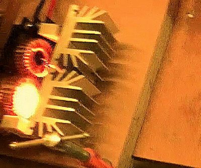
Not sure which goes first, the chicken or the egg, but the Mosfets sure can heat up and go "boom"! To make things worse,(and I can't believe they did this) there is
absolutely NO sign of heat sink compound on any of the 6 Mosfets that I have removed!!!
But, I actually found only 2 of those 6 Mosfets to be bad. Every one of my three bad boards had ONE bad zener diode.
The only other component that I can point to was that one lead on one of the 470 ohm resistors had actually broken and was making only intermittent contact with its
pad.
What made this a bad deal is that this was on a board that had previously failed. Not sure which one. Before I discovered the bad resistor lead, I had decided
to simply replace the Mosfets and nothing else.
A bad idea, looking back. Those 470 ohm 5 watt resistors are relatively heavy and they stand on end. I have ho idea how much vibration that board may have been
subject to on its long way from China. I don't know whether that bad resistor connection had caused the original failure or not.
But, when i powered up the repaired board, I saw a quick, large deflection of the ammeter, and then nothing.
I just completed a successful complete active component replacement of my best chance board. I added wire to the Mosfet traces that had been compromised.
Being worried about heat transfer from the Mosfets to their heat sinks, I bought the most expensive thermal grease (or whatever you want to call it) that I could
find at Radio Shack. Of course, simply FINDING a Radio Shack store is a problem in itself these days. And, of course, I applied it to the Mosfets at their heatsink
junction.
The board powered up properly and I have run about a half hour worth of experiements while carefully watching the ammeter and keeping the current below 20 amps.
All of the experiments went well and the board is still "alive".
Note: I am supplying the board with 24 volts from two 12 volt batteries in series.
I tap off 12 volts from the larger of the two batteries to run the fan and water pump. They are on a separate switch, so I can keep them on after I shut off the
power to the induction heater.
My heat exchanger's radiator heated up by about 20 degrees F during this testing, and the Mosfet heat
sinks temperature increased by about 10 degrees F above ambient.
The ammeter that I am using is a cheap one and I am not sure how accurate it is. So next on my list (it's getting longer, isn't it?) is to find my 50 millivolt
shunt and install it into the circuit so I can measure the voltage drop and accurately calculate current flow..
A curious discovery:
I just got a little graphite crucible in the mail yesterday. It's the one that several youtuber's show heating up solder or, in one case, aluminum.
What a surprise when I put it in the work coil---- the current shot up over 30 amps (pegged my meter)! So I immediately turned it off, not wanted to toast another circiut board.
How the heck do the youtube guys get away with that?
I will try it again when I trust my current measuring device.
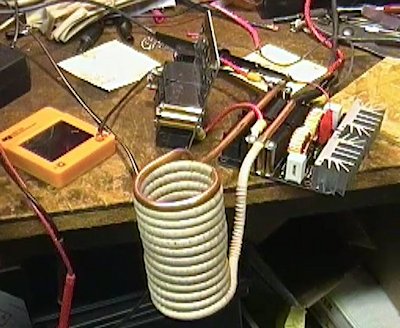
Some of my ZVS Induction Heating Toys
Update December 3, 2016:
Since the crucible's coupling caused such high current to flow in the system, I made a smaller graphite crucible from a 1 inch diameter graphite
rod that I had in stock, so I could see what difference poorer coupling might make.
The larger Crucible is the one that comes with the induction heater.
I made the small one by simply boring a 5/8" hole in a one inch rod graphite rod.
It only caused about 8 amps of current flow. I got it to heat up to about 800+ degrees F, but then my battery voltage started to drop
so I discontinued that test.
I also checked the accuracy of my little analog ammeter by putting it in series with a high quality 50 millivolt shunt. Surprise! My cheap meter is "right on"!
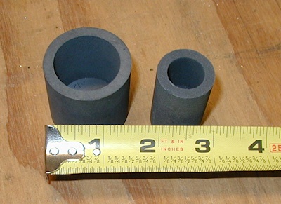
Well, I just received ANOTHER (yes, my 4th!) 1000 watt induction heater kit in the mail. It is just like all the others, except for one very interesting item:
The diameter of the work coil is about 3/8 inch larger in diameter than the other 3 work coils that I have!
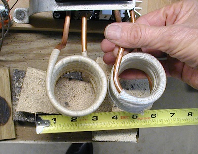
Note the difference in diameter of these two work coils.
I already did understand that one needs to fit the work coil to the job,
but I was about to find out just how sensitive this particular ZVS system is
to a change in coil size.
Knowing how the system responded to the smaller crucible, I decided to try the larger crucible with this larger work coil.
Viola!
Now the system only draws about 22 amps, as opposed to the 30+ amps that it drew with the smaller diameter work coil.
Just as the crucible started to glow, the battery voltage started to drop agian, so I had to terminate that test, too.
I recharged the batteries and started the test again. This time I noticed how much the Mosfet heat sinks were heating. In an attempt to
increase air flow, I pushed my little fan closer to the the pc board, and in so doing, shorted across the work coil, blowing one Mosfet and at least
one zener diode.
So, it's back to the bench to replace components.
Before I go back at it again, I will replace my smaller (garden tractor) battery with a full size car battery and,
I will make a new, nonconductive, fan mounting bracket and move the fan as close as possible to the heat sinks.
An interesting point: the capacitors don't seem to heat at all, even though the Mosfet heat sinks have been heating to about 120 degrees F.
toward the end of my tests, now that I am drawing a bit over 20 amps at about 24 volts.
December 8, 2016:
I repaired two of my boards. The general approach is to replace all 4 diodes and both Mosfets, plus anything else that is obviously wrong.
I'd call that "shotgunning", but that's the way it is for now. becuase, even though I attempt test or at least ohm out the parts that I remove, I
am not sure if I have stressed something or not.
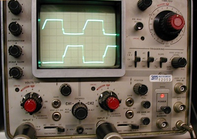
Here's the test setup that I used just to see if they worked:
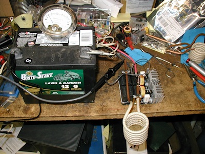
Using a 12 volt garden tractor Battery, Note One Amp at idle. Output Across Work Coil. Just about 100 Khz
Neither one worked after the parts replacement.
On one of them, I had re-installed a used Mosfet that had tested okay. when I hit that board with 12 volts, it pegged my 10 amp meter.
I will replace that Mosfet and try again.
The other one did absolutely nothing when I fired it up. Upon close examination, I found the the heavy trace between the Positive power input and the "chokes"
had actually blown right off the board for about a half inch. That area had been hidden by the toroid above it. I Replaced the missing piece of
copper with some de-soldering braid and now it works.
An interesting note:
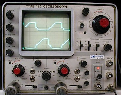
I decided to 'scope Gate-to-ground for both Mosfets. I was surprised to see that there is measurable difference in the two signals:
The upper signals are Gate to Ground. The lower signals are work coil to drain.
Q1 on the left and Q2 on the right.
Not sure what to make of this. It almost HAS to be a difference in the characteristics of the two Mosfets.
Now I suppose I will have to make the same measurements on a couple of other boards.
6. Operation and Testing
January 12, 2017:
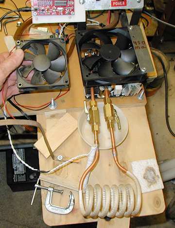
Larger Picture of my 4th ZVS Induction Heater setup
Well, I just got a new test setup built, one where I can use either 24 or 36 volts to supply the ZVS heater PC Board. It worked well enough for me to
shoot a youtube video that is good enough to present:
First Youtube Video test of my fourth setup
I twisted the power leads from the batteries as much as I could to cancel out stray inductance, attempting to clean up the gate drive signals.
That my have worked, since the Mosfets stayed pretty cool during this test. But I still think I need to 'scope the gates.
Now I will have to start playing around with various sizes of work coils.
Or, I could begin to work on reducing the operating frequency.
Or----?
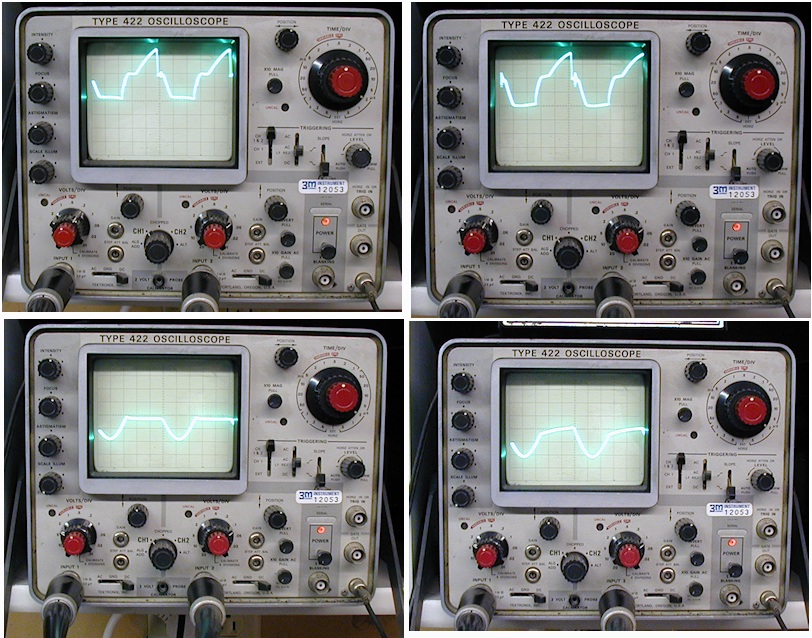
January 16, 2017, 'scoping the Mosfet Gates:
This is a report on the the Gate drive signals from my latest setup. In my Jan 12 post, above, I explained that I had twisted the power leads.
It appears that the twisting made a BIG improvement.
Here is the result:
Gates with 24 volts applied to the circuit, with circuit "idling"at about 2 amps.
Gates with 24 volts applied to the circuit, with circuit loaded to 8 amps.
Gates with 24 volts applied to the circuit, with circuit loaded to 22 amps.
There is hardly any change at all in gate drive wave shape at different currents.
Now compare these gate drive signals to the pictures in my December 8 post. You can easily see that the gates are "full on" for
a much longer percentage of the time with this setup.
At any rate, those Mosfets sure do stay a LOT cooler this way!
If you look carefully at the waveforms, you can see that the tank frequency slows down a bit as the current goes up. I estimate that the frequency drops
from about 100 KHz at "idle" to about 90 KHz at about 25 amps.
But---- back to the wave SHAPES--- it looks like there's one other possibility for the poor wave shapes from Dec. 8. There I was only driving the circuit with a 12 volt
garden tractor battery. What if that voltage wasn't enough to supply a full 12 volts to the gate by the time it passed the 470 Ohm resistor? Would that
situation have kept the Mosfet in its linear region for a longer part of each cycle? Another thing to test, I guess, but I'm pretty happy with the results right now.
Of course, if you look closely at any of the gate traces, you can see that one Mosfet seems to be turned on for a bit longer than the other one.
Is it a difference in Mosfet characteristics? Variations in the actual recovery speed of the "FAST" diode? Hmmmmm.
January 26, 2017: Actually reading frequency and an interesting 36 Volt observation!
My third youtube Video, Last Attempt to Understand the "Glowing" Phenomenon
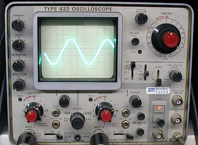
This time I have added a cheap (USD$50) oscilloscope to read one gate, but this 'scope also gives direct frequency read outs and that's why I attached it.
Here's how the instrumentation looks right now:
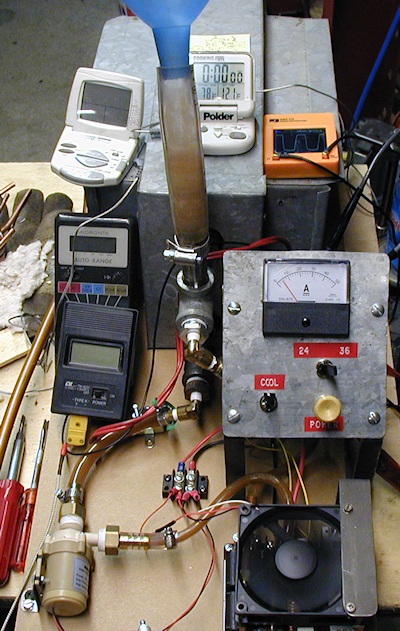
See the little Orange colored device at the upper right? That's the 'scope that reads frequency directly.
Here's a picture of its current reading:
The frequency drops to about 83 KHz with when I insert the 5/16" by 3/8" steel bar into the large work coil that you see here.
Now that I have a way to actually measure frequency, I can start to add Capacitance and Inductance to the resonant tank circuit and know what
the results are as I attempt to get steel up to higher and higher temperatures.
Now, HERE'S the latest thing----
I just now added some tie points on the system to make it easier to connect to the gates so I can both read frequency and 'scope both gates on my
"real" oscilloscope.
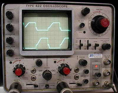
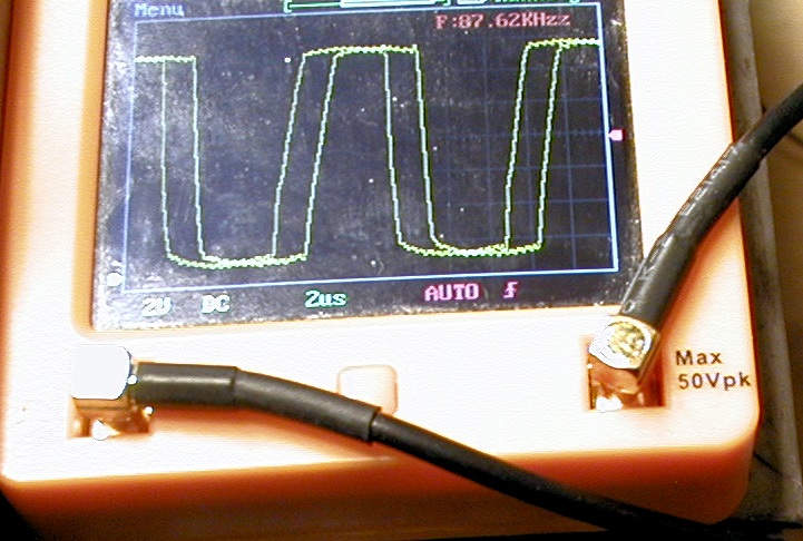
So, Here's what the gates look like at 36 volts:
Note that the gate signal is almost a square wave!!!!
That's great, becuase it means that the Mosfets will turn on FULLY more quickly!!!!!
Which means they won't heat up as much as they would if they turned on slower.
To me, this is a BIG deal. If you look back to earlier posts on this page, you can see how poor the gate turn-on waveform is at 12 volts.
You can see that it gets appreciably better at 24 volts.
And now--- it's even BETTER at 36 volts.
February 9, 2017: I finally got to 48 volts and I put up two more videos. See the new video links at the top of the page.
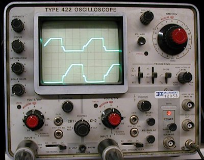
Here's the gate drive story to date:
Summary Finding:
The higher the input voltage to the board, the FASTER the gates turn the Mosfets on fully. This means that the Mosfets will run cooler because
they spend less time partially on.
Note:
The voltages in RED (in the picture below) on each trace tell you the voltage applied to the PC board when each picture was taken.
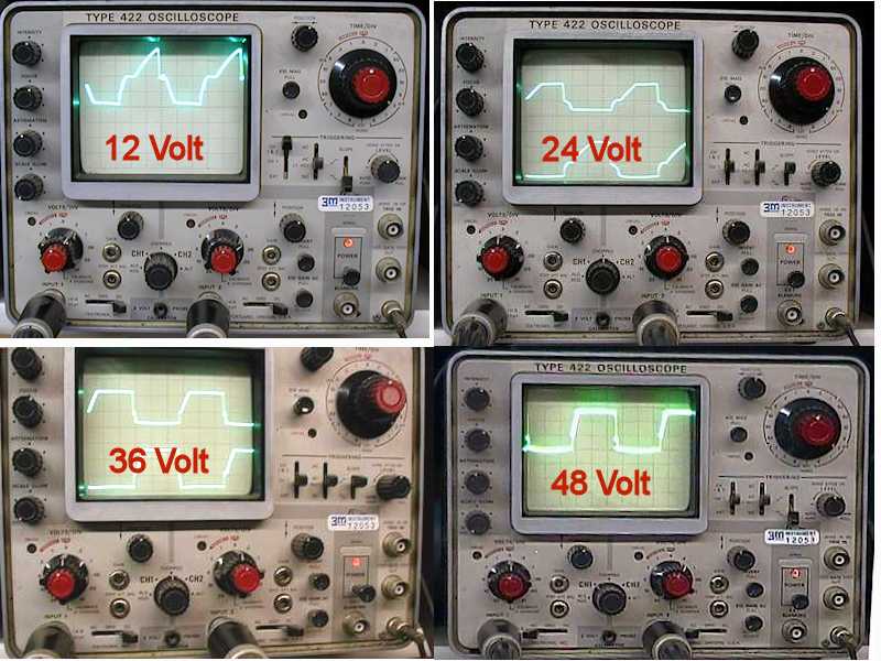
Don't pay any attention to difference between the maximum amplitudes of these signals from picture to picture. These pictures were taken many
days apart and I had been messing with
voltage calibration for various reasons. You can pretty much assume the that highest reading in each picture is 12 volts, which occurs
when the 12 volt zener diodes turn on.
It's WHEN the voltage reaches its peak and the square-ness or width of the gate signal that we are interested in.
The faster we get the Mosfets fully "ON", the better off we will be.
A "Perfectly Square" wave means that the Mosfets go from completely OFF to completely ON in ZERO time.
Therefore, they won't be in their linear region at all.
Okay, so nothing is perfect.
But the closer we get to "perfect" the cooler the Mosfets run.
March 6, 2017: Getting the Resonant Frequency of the system lower and lower
I have read that lower frequencies make the energy penetrate deeper into the work. For ferrous metals, anyway. So, to get the maximum efficiency
of energy transfer to ferrous metals (iron and steel, mostly), I need to get the frequency down a lot lower than it is with the "stock"
1000 Watt 12 to 48 volt ZVS Induction Heaters that I am playing with.
See "Part 6" at the top of this page for my video of finally getting the frequency down to the 38 to 40 KHz range. I did it by doubling both the
capacitance and the inductance. I doubled the capacitance the same way I did earlier, but I wound a 12 turn copper coil for this test.
But, since I was only using my 12 volt setup for this test, I could only draw about 8 amps of so.
So the next step will be to duplicate that test on the 48 volt air and water cooled system.
March 10, 2017: I recently went a little off-track by performing my first MOT (Microwave Oven Transformer) rewind.
You can see the result as the "Part 7" Video, above.
I started that process so I could build a power supply for this induction heating project. I'm not there yet, but I think I can come
pretty close to a 48 volt secondary winding with a single 14 gauge enameled secondary or maybe 3 or 4 16 gauge enameled "bundled" wires.
As I have mentioned earlier, I already have a nice 48 volt, 26 amp commercial power supply, so I don't need to rush into this job. But I DO want to get
it done!
I don't know how many different sizes of MOT are out there. I already have one that is larger than the one I rewound for this video. And I will
continue to look for larger ones. I used this smaller MOT just to get some experience with using enameled wire.
Recently, a friend asked several good questions about that process. I answered him, but thought I'd add those answers here:
Pete, I just watched your MOT coil winding video with the four strands of wire run together. This was very interesting and helpful to see it done.
I really appreciated your charts with the results shown at the different resistances.
It looks like this will be a very strong power supply when finished.
Ans: Thank you. I just got an even bigger transformer to work with, too.
Remember, though, this was just a method of getting some hands-on experience with the MOT and the enameled wire. I don't know if I
will ever use that one in a project, but at least I do know what its capabilities are.
Question 1:
- How did you connect the two sections of wire together?
Ans: I bolted the ring terminals of the first and second winding sections together.
Question 2:
Did you scrape off the enamel and then use in-line crimp type connectors?
Ans: Yes and Yes. That particular wire was from a local electric motor repairs shop and of pretty high quality insulation.
After I had thought that I had sanded all the "varnish" off (with 150 grit emery cloth, I found that I still couldn't tin it.
So, looking more closely at the "stripped" ends, I saw that I hadn't really gotten all the way through.
So that's when I got out the razor blade and went at it again. Then sanded some more. But with 80 grit emery cloth.
After all that, the wire tinned just fine.
Question 3:
Did you solder them also?
Ans: Yes, I did. I soldered all four leads together, crimped the terminal onto them and then soldered the terminal to the wires.
I learned this requirement the hard way the first time I added capacitors to the induction heating circuit.
Question 4:
- Do you think the four wires together are working the same as a single larger gauge wire would in this same application?
Ans: In general, yes. However, I had to use 19 gauge wire for this one because the motor shop didn't have anything heavier.
If you look up ampacity tables for copper wire, I think you will find that 19 GA comes in at about 1.9 amps.
I originally wanted to emulate 12 GA, at 20 amps, so technically, I am off by a factor of 20/7.6= 2.63.
But it didn't seem to be much of an issue. Those tables make some assumptions about heating due to insulation,
etc.., so I think there is some room to fudge. (I had wanted 16 Ga, by the way).
Question 5:
- Have you done any winding resistance tests to see if you can calculate the turns ratio, primary to secondary, required to produce 48 volts?
Ans: The math would have to do with the efficiency of the transformer core and some rather esoteric considerations that are currently beyond me.
Besides, I saw one video where the guy simply wound 10 turns on and measured the output voltage. He calculated the volts per turn and went
on from there. It worked out pretty close for me, too.
Question 6:
Instead, could you have just unwound part of the existing secondary winding to get to around 48 volts?
Ans: Technically, I think that would work, but once you see how fine that wire is, I think you will abandon that Idea.
Those secondaries produce anywhere from 2000 volts to 4000 volts (like the ancient AMANA RADAR RANGE that I just tore apart).
At 0.7 volts per turn, as an example, there'd be about 2800 turns on the secondary. You'd have to unwind the first 2750 turns or
so to get into the range of usefulness, right?
Question 7:
---Or, would that finer wire on the secondary not have produced the amount of amps you wanted?
Ans: Corrrect, It wouldn't come anywhere near handling enough current.
I'd estimate it at 36 ga. or even smaller. That's about 0.21 amps on the ampacity table, about 1% of what I need.
Quesstion/Comment 8:
I was at the Tractor Supply Store in Inver Grove Heights today and saw that they have #4 and #2 gauge multi-stranded wire for making
replacement welding leads by the foot. It does however have very thick rubber insulation so the turns will be quire limited.
Ans/Reply: Yes, that thickness of insulation IS the problem if you are trying for higher voltages. But those big wires seem to be exactly what the guys who are making spot welders are using.
For a spot welder, I think they use only 2 turns. But I don't think you'd use one of them to weld your car body to the frame.
March 23, 2017:
I have recently moved the "40KHz" parts up to the 48 volt system.
I had previously shot 3 segments for a next video, but I wasn't quite ready to assemble and publish it yet. Today I got my cooling water too hot,
so I need to add a fan to the radiator. I also need to baffle the fan I added to cool the extra capacitors because it blows too
hard on the work coil, cooling the work inside it.
A day later: I added a bit that video, edited it some more and have decided to publish it. See "Part 9" at the top of this page.
Some of you will find it useful, but it is getting pretty long (currently just under 36 minutes).
Sometimes I think it's good to show things in real time, but I appreciate that it might bore some people,
so I have taken my best guess for correct balance.
The good news is that I am still using the same ZVS heater pc board that has been on Setup #4 since ever since I built it up
with the switch panel. And that's while I have been abusing it at 24, 36 and now 48 volts. In today's tests, I even had unplanned current excursions up
to 35 amps or so with no ill effects.
March 30 and 31, 2017:
On March 30, I updated my setup by:
- adding a water cooling fan to the heat exchanger, with an exit air temperature meter
- adding an air deflector for the fan that cools the added capacitors
- removing the water pump and cooling fans from the main power supply current shunt (so I'd be reading system power more accurately)
Note: In all past tests, the 2 amps that these components draw have been adding to the "apparent" idling current.
-added a meter to read Mosfet temperature
-and a few other "cleanup" items.
Now I want to see what advantage there is, if any, of running at 40KHz vs. approximately 100 KHz.
So I ran and video taped an extensive test, with this goal in mind. During this test, I retested every metal that I had acquired data for in past tests.
For most metals, I simply checked their initial current draw.
Everything stayed nice and cool, but I wasn't pushing for long periods of high current draw.
At the end of that test, I forged a couple of pieces of steel that had been heated in my setup, just to show that it can be done.
That video is Part 10 at the top of this page.
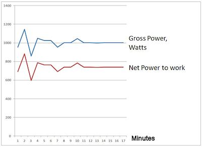
On March 31, I ran a non-video taped test to see how the new cooling system would respond to continuous higher currents. This test lasted 15 minutes, with
an average current draw of 16 amperes at 48 volts, producing a total of 768 watts.
I was very pleased with the results. Everything stayed nice and cool.
On April 1, I reran that test, but I pushing the average current up to about 21 amps for the whole 15 (actually 17) minutes.
Here is a link to the Excel spreadsheet that details March 31 test:
15 Minute Test at 16 Amperes
April 2, 2017:
The focus of this video is on running the system at 1000 watts total work coil current at 20 amps or more for
a full 15 minutes (actually about 17 minutes) to get a complete temperature profile for the system.
The weight of the steel that was being heated in the work coil was 290 Grams. or about 10.2 ounces.
It is Video Part 11 at the top of this page.
I suppose the next thing to do is to return this exact setup to a frequency of 78 KHz by removing the second set of capacitors and installing the
6 Turn 2 inch ID work coil. Then I should and rerun the same, identical test so we
can determine the value (if any) of 43 KHz operation.
April 15, 2017:
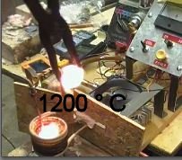
On April 9th, I a test similar to the previous one, but at 87 KHz, so I could compare 87 KHz runs with 43 KHz runs. This time, I did measure the
temperature of the work, a thing I should have done in the previous test.
It is Part 12, up at the top of this page.
I severely edited this video but also included my comparison analysis of the two tests and more.
I divided this video into 4 sections, so you can see most of the test itself (if you have the time), or, you can view just the
comparisons, my thoughts on future process changes and possible practical uses for this particular Banggood ZVS 1000 Watt 12-48 volt Induction Heater.
Here's a bunch of stuff most of which I didn't include in the video:
Summary, first look:
Too bad that I hadn't taken the work's temp in the 43 KHz run.
But I did get to 1201 C at 87KHz. That's 2194 F. My original goal was to heat a piece of half inch square bar to 2200F. close enough. I got there!
Q!: what's the highest temp I have previously recorded, and at what frequency?
A: march 31, 1039C. 40 KHz, 16 amps
A: march 20, 1120C, 9 min 12 amps 43 KHz, "Pushing the Limits"
A: Feb 9, 1090C first recorded 48 volt test, a single, insulated cylinder, I think.
*** Note!!! this was at 87 KHz, but, when I added caps, temp went up FAST and Cap wires got hot FAST!!
A: All of my ealier tests were at 36 volts and below, so I don't think work temperatures would provide useful comparisons here.
Also, I forgot to measure the chokes. But, I think the "PC Board Under the Mosfets" temperature measurement IS related to chokes because of
heat transfer from them to the heavy PCboard traces.
The Mosfets stayed about the same.
The Biggest difference is that caps got hotter at 87 KHz and had not stabilized by end of test.
Regarding the smoke and the sudden temp rise as water started to boil within the coil once the insulation turned black at the end of the 87 KHz test:
To deal with that issue, I have ordered some 1/8" thick 2300+ degree F. thermal "board" insulation to replace the two kinds of fiberglass sleeving
that I have been using up till now to insulate the coil windings from the work.
Description:
INSWOOL 2300 PAPER, Flexible Refractory Paper
I will make tubes from it that will fit just inside the work coil. That way, it'll be easier to install and to replace insulation if anything happens to it.
Conclusions:
I should have measured the work temperature during the 43 KHz test. Maybe I should rerun the 43 KHZ test, measuring the work temperature.
I should have reconnected the work coil water tubing correctly before running the 87KHz test to avoid the spot boiling at the very end of this test.
During an earlier test of the standard board, at 87 KHz, where I only connected the second set of capacitors for a short period of time,
I noticed that the temperature of the work rose rapidly. But the wiring to the capacitors heated so rapidly that I had to disconnect them.
***Maybe I should investigate this phenomenon more carefully.
?? But, didn't I run one of those earlier tests with only double caps? Oh, yeh, I'll bet that was test at only 12 volts on my small system!!!
Hey, I wonder if this induction heater would work well as a demagnetizer!!!!
July 8, 2017:
This note relates to heating of the capacitors.
Over the past several months, I have watched a number of videos where the author talks about the capacitors heating up a lot.
I have not had much of a problem with capacitors heating. I wondered why others did.
Well, recently I was preparing a simple, portable demonstration using the basic Banggood board, powered by 2 garden tractor batteries, for a
total power supply of 24 volts. I was fan cooling the board, but not water cooling the work coil.
After only a minute or so of operation with various ferrous materials in the work coil, drawing 10 to 20 amperes, I realized that the copper work coil tube had
gotten REALLY HOT!! It got so hot, in fact, that the longest end of the work coil, which sits directly over one set of capacitors, was tranfering a LOT of heat
to those capacitors.
So my point here is that:
-If you don't water cool the work coil, you will seriously heat up the capacitors closest to the long work coil leg!!!
October 23, 2018:
Changing coils without getting water all over the place:
It has always been a messy job to change work coils. First because of the way they are screwed down to standoffs on the board, but mainly because I have
to deal with water running out of the cooling system and onto the workspace or the floor.
So, I added a couple of quarter turn ball valves this way:
I think I wanted to go with flare fittings, but I didn't locate any valves that worked that way, so I went with compression fittings.
That's what you see in the picture.
Maybe you already know this, but copper tubing is sized in two different ways. If you go to the plumbing department in the hardware store (USA) and ask for "quarter inch" copper tube,
you will get tubing with a 1/4 inch OD, but if you go into the Mechanical tubing world, I think "quarter inch" refers to the ID.
Anyway, the quarter inch OD tubing is the size I use for all my coils.
I got those valves at Faucet depot:
Faucet Depot Valves for Work Coils
I think that is the one that I used.
I used compression fittings since the ferrules are smaller than the flared part of flare-type fittings, which would have made it easier to insulate the coils with sleeving.
Or, in some cases, to replace the sleeving if I do something bad to it.
BUT!!! I totally forgot that the nuts have to go on before you put the ferrules on. So, you have them in the way for insulating or re-insulating anyway!
So, I guess it really doesn't make much difference which way you go.
May 22, 2019:
Installing a larger cooling fan
When testing Brass Cartridge Casing annealing recently, I noticed that the capacitors on the board were getting warm, which is nothing new and they were not
getting anywhere close to "too hot to touch". However, I did realize that the 90 mm diameter fan that I have been using to cool the circuit board all along
was not quite large enough to blow on the 2 outer capacitors. So I bought a 120mm fan and replaced it today.
Here you can see the difference.
I still need to add a bulkhead to separate the board from the work coils so the fan doesn't blow on the work coil which can cool the work.
Adding the bulkhead, as I have done on my 2500 watt unit would also be a good idea to take stress off the board's coil standoffs when changing coils
At some points, I have used a second fan to cool additional capacitors when experimenting with doubling capacitors, too.
May 22, 2019 (Continued):
Adding a frequency counter to this system:
A while ago I added a frequency counter to the 2500 watt system so I can see how coil design affects gate signals.
More recently, I added one to this 1000 watt unit too.
It has been very useful when working on the "annealing" work coils.
Here, in this 2500 Watt Video, I describe the freqquency counter in some detail:
Frequency Counter Explained
That video also talks about other 2500 Watt system improvements, too, but I hope it tells you enough about the counter itself.
July 4, 2019:
Brass Cartridge Casing Annealing
I don't do any cartridge reloading myself, but over the last couple of months I have been testing various work coil designs for that process.
There are many folks out there who are already doing this, many using one of these 1000 Watt ZVS Induction heaters. My testing is mainly focused on making
coils that heat the casing quickly, while making sure that the heater's components are not overstressed.
I think I have accomplished that goal, as you can see in my youtube videos- Part 13, 14 and 15 at the top of this page.
August 8, 2019:
Testing a large (10 inch OD spiral or "pancake" coil)
I made this coil just to see if it would have any usefullness in annealing thin sheet metal. See the video in Part 16 in the navigation bar.
This work coil has the highest inductance of any coil I have made so far and runs at a much lower frequency. This lower frequency produces very sharp
square wave gate signals, which is a good thing to minimize Mosfet heating.
May 6, 2020:
Notes on the negative effects of increasing operating frequency of the ZVS induction heaters:
---------------------------------------------------------------------------------------------
Many of you are probably tired of hearing me talk about being careful to keep the Mosfets from spending much time in the linear mode.
But here I go again:
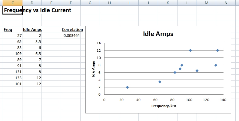
We can easily see that the idle current varies when we change work coil designs.
From my own work coil data spreadsheet, I recently noticed that idle current and frequency seem to vary together.
When I plotted 9 pairs of idle current versus frequency observations, I could see the relationship easily.
I got a correlation of about 0.8. Of course "correlation" does not necessarily equal "causation", but it seems reasonable to me.
I see this relationship as another indicator that higher frequencies create more lost power within the ZVS circuit components themselves.
This, in turn, leads to more stress on, particularly, the Mosfets and the tank capacitors.
But why do we care, as long as things seem to work okay?
Well, here are a couple of reasons:
1. Assuming that you or your system has a maximum safe current limit, the higher the idle current, the less current there is available for heating the work.
In my case, the maximum sustained current that I will allow on my 1000 watt unit is about 22 amps TOTAL. And, for my 2500 watt unit, it's 50 amps, TOTAL.
I hope that is clear to everyone.
But--- I think this item is even more important:
2. The Basic ZVS power circuit that most of these Chinese ZVS induction heaters use works most reliably at a frequency below about 100 kHz.
And, the lower, the better, in my view!!!
So, when you design a new work coil, you need to know whether it will overstress the system or not.
You can quickly check it out by powering the system up and noting the idle current.
That current is primarily heating up the Mosfets and the Capacitors. Of course it also heats the work coil,
but as long as we are water cooling it, we won't worry about that.
If the idle current is higher than about 8 amps, I think you will be stressing the system more than it was designed to be stressed.
See Chart:
Please, Please, Please contact me if you have anything to add or if you think I have missed something or I have gotten something wrong!!!