Work Coils for ZVS Induction Heater
Last updated: October 19, 2023
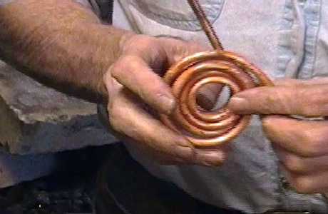
A newly made 2 Turn by 3 layer Work Coil
Can I predict the operating frequency using a simple formula?
Recently, I got this comment and question:
"I don't see any mention of using the standard LC formulas for resonance to calculate your coil dimensions
for adjusting your output frequency. Are they valid in this application? "
Here is my answer:
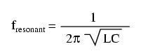
Yes, the standard resonant frequency formula is a good place to start.
In fact, I keep a spreadsheet where I have it set up to make it easy to play "what if" when I try a new coil design.
However, as you probably already know, the standard formula assumes you know EVERY source of L and C in the circuit.
So simply plugging in the L of the work coil and the C of the tank caps that you see in a schematic doesn't tell the whole story.
But it's a good starting point.
For instance, recently I made a fairly large pancake coil; its OD is 11 3/4 inches.
The predicted Frequency was 23.344 kHz, but the actual measured frequency of the system was 18,720 kHz.
So you can see that using the formula definitely puts me in the ballpark, but it's off by about 20 percent. That has been pretty typical.
That formula doesn't deal with the "Q" of a circuit, either, nor does it "know" the effect of frequency on Mosfet turn on time, etc..
How to make work coils:
---the way I do it
As they say, "there are many ways to skin a cat", so I am not telling you that this is the only way that work coils can be made.
What follows here is simply the way I choose to make them, so far:
-I make all of my coils using a material called "(soft) copper refrigeration tubing".
-Almost all of my coils, so far, have been made with 1/4 inch OD tubing, but I just made one using 1/8 inch OD tubing, so I could make it smaller
in ID without it flattening.
-I always water cool my work coils.
-I always insulate my work coils.
-Basically, I simply wind them around various mandrels. In my experience, the minimum inside diameter is limited to about 3/4 of an inch
for the 1/4" OD tubing with the process that I use. But inside diameters below about 1 3/8 inches require some special care.
-For the one coil made from 1/8" OD tubing, I easily wound it on a 5/8" diameter mandrel with no flattening issues.
Here's my very detailed video on my methods for making work coils:
How I Make Work Coils, in Great Detail