Pete's 1000 Watt 12 to 48 Volt ZVS Induction Heater Troubleshooting Guide
Created: February 2, 2017
Last Revised: October 18, 2023
Home
Computing
Back to ZVS Stuff
Contact Us
First:
Try to figure out WHY it failed.
This is so you can attempt to eliminate any future failures from that cause, for instance shorting work coil windings together.
I have eliminated that problem by covering the work coils with high temperature (240 degrees C) fiberglass sleeving.
NOTE: In my opinion, you MUST have an ammeter in the power supply circuit, because it is all too easy to put something into the work coil that
will cause an excessive current flow. If you drew more than about 25 amps for any length of time (over 30 seconds or so),
you probably blew a Mosfet or two and a couple of zener diodes. This will be especially true if you haven't added heat sink compound
to the Mosfets and if you are not fan-cooling the board.
Second:
Get a copy of the schematic. (See Below)

Watch this youtube video to learn how Mosfets work:
How Mosfets Work
A few general notes:
Look for signs of physical damage to the Mosfets, Diodes or Resistors. Replace them if there is any physical damage .
I had one board where the heavy trace from the positive power terminal had evaporated for about a half inch length. I soldered
a piece of heavy copper braid over the break (after replacing some failed components) and it works fine now.
So far, the main failure components have been the Mosfets, and the 12 volt zener diodes.
In a couple of cases, the 10K ohm resistors that sit right beside the zeners have actually burned.
I think that was because of the catastrophic failure of Mosfet that is very close to them, not that they failed from over current.
The Mosfets have failed almost every time the board has stopped working.
3. Start by testing the board before removing any components:
-Check Resistance from the DC input connections, Plus to Minus
Digital ohmmeter set on about 2K scale.
Good reading is about 5.1 K ohms to 5.3 K ohms, either way with meter leads
A Resistance reading of about 600 ohms means that one zener diode (D1 or D2) is probably shorted.
(It may not be a dead short), but if it is bad, if will probably show a low resistance both ways.
If both zeners are shorted, I read about 230 ohms with this test.
Various resistance readings for one "Good" board:
Work Coil to Work Coil = Zero Ohms (Why Not? It's a BIG copper Tube!
DC Input Terminal (-) to Work Coil either side = ~5.25K Ohms
DC Input Terminal (+) to Work Coil, either side = 0.0 Ohms
DC Input Terminal (-) to D1 Cathode = ~5.25K Ohms
DC Input Terminal (-) to D2 Cathode = ~5.25K Ohms
Across D3 or D4 (either way with probes) = ~450 ohms
Note 1: For all the readings above, you should get the same resistance with the ohmmeter probes either way.
Note 2: All of these readings are approximate because of the tolerances of the various components.
4. Replace the suspected components, then test them, Out of Circuit to verify your diagnosis
IRFP260N Mosfet information:
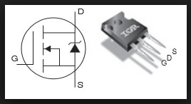
What makes for a GOOD IRFP260N Mosfet?:
Ohming out a Good Mosfet, out of the circuit:
Gate: to any other pin, Resistance = Infinity (up to 20 Meg Ohms scale on digital VOM, either meter lead to gate.
Drain: +D to G =infinity; +D to S = infinity
Drain: -D to G = infinity; - D to S = about 7.26 Meg Ohms
Source: + S to G = infinity; +S to D = about 7.26 Meg Ohms
Source: - S to G = infinity; - S to D = infinity
Drain to metal backside of Mosfet = 0.0 ohms
History of failure mode for 8 IRFP260N's / Physical Appearance:
---------Analysis----------------- / Physical Appearance
1. Gate shorted to drain / Normal
2. Everything shorted together approx, 0 Ohms / Scorched
3. Everything low resistance to everything else (150K Ohms) / Scorched
4. Everything low resistance to everything else (10K Ohms) / Normal
5. Everything shorted together approx, 0 Ohms / Gate Blown Off
6. Everything shorted together approx, 0 Ohms / Source Blown Off
7. Everything shorted together approx, 0 Ohms / Source Blown Off
8. Everything shorted together (18 to 60 Ohms) / Normal
12 volt 1 watt Zener Diode information:
I have replaced 9 of them so far and here's what I have found when I measured them OUT of the circuit:
5 of them were shorted, zero ohms either way.
1 was physically broken
1 of them read 3 megohms with anode to negative meter lead and it read 0.7 megohms with anode to positive meter lead.
This was with my meter set on the 2 megohm scale.
2 of them read "good". Here, I set the meter to the 200 megohm scale. I get 1.2 megohms with the positive meter
lead to the anode and I get infinity with the negative meter lead to the anode.
FR307 Diode information:
As an "insurance" measure, I have replaced 7 of them so far but they all seem to be good when tested out of the circuit.
With the diodes OUT of the circuit:
And, with my meter set on the 2 megohm scale, I get 0.7 megohms with the negative meter lead connected to the cathode and
I get a reading of Infinity with the positive meter lead connected to cathode.
As you can see from this, none have failed during the events that caused other parts to go bad.
Note 3: It's probably pretty obvious, but readings that are significantly higher or lower than those shown
in any of the tests above mean that something is either open (high) or shorted (low), like the blown board trace that I mentioned
at the beginning of this page.
5. Testing the repaired board:
Before powering the board up, perform the resistance checks again. Just recently I repaired a board but DC terminal tests showed about 10K
ohms instead of about 5K ohms. It took me several minutes to locate the problem; one Mosfet Source pin wasn't making contact with the top trace at
the top side of the board because it had been burned away. I had to remove one of the 470 ohm wirewound resistors to get at the pin to make a good
solder connection. It I had looked more closely, I might have seen that issue before I put the Mosfets and heat sinks back on.
Now,
connect a 10 or 20 amp analog ammmeter in series with an SPST DC rated switch, and a 12 volt car
or garden tractor battery. The idea here is to be able to verify that all bad components have been replaced without destroying
more stuff if you missed something.
Limiting the input power by limiting the input to 12 volts will give you time to shut off the power if there's still a problem.
-Connect the ZVS Induction heater board to the power circuit (with the switch off) carefully observing correct polarity.
-Flip the switch on. being prepared to turn it off QUICKLY if the meter pegs or goes above 4 or 5 amps
-The idle current should be between 1 and 2 amps with a 12 volt input and the "normal" work coil (with NO work in it) attached.
If the idle current IS too high, or is zero amps, go back to Step 3 and retest the board, to determine what else needs to be replaced/repaired.
-If the idle current tests okay, the board is probably good:
Continue testing by slowly inserting a steel bar of about 1/4" square to about 3/8" square cross section into the work coil.
Watch the current rise. It should rise by several amperes by the time the test bar has been fully inserted.
Don't continue this test for more than a few minutes. After all this work, you don't want to overheat anything!
Next step is to add a cooling fan for the board, a water pump and heat exchanger for the work coil,
and an in-line 20 amp circuit breaker before going to a higher supply voltage.
I hope this procedure helps you to get your board working again and to make it less likely that you will have any more failures.
Please, Please, Please contact me if you have anything to add or if you think I have missed something or I have gotten something wrong!!!