Pete's Power Hammer
Die Cavity Restoration Method
Last Revised: October 20, 2023
French Creek Valley Home
Back to Blacksmithing
Back to Powerhammers
Contact Us
Restoring Power Hammer Die Cavities with a Skil Saw
(and Some Elbow Grease)
By Pete Stanaitis
If you plan to replace the dies in your Little Giant/Mayer Bros power hammer, you will probably find that the die cavities are somewhat chewed up from
loose dies bouncing around. You need to true these cavities before installing new dies or you will be resetting dies for the rest of your days.
There are probably as many ways to do this as there are blacksmiths.
Here below, is one of those ways. Although the focus here is on the lower die cavitiy, much of this will apply to the hammer head or ram, too):
But, since the ram is made of steel, not of cast iron, I think you will find its die cavity in much better shape than the lower die cavity.
Part A:
Andrew Townswick, a Blacksmith from Decorah, Iowa, tells how he did it, 6/27/2002
Andrew:
"The bottom die cavity of my power hammer was dished out quite a bit from repetitive hammering on loose dies. The lower die had beaten itself down
into the main hammer casting by about 1/4" or so. I wanted to install new dies and have them fit properly, so I needed to clean up the bottom and
sides (dovetails) before attempting to install the dies.
I saw something a while ago about Ollie Juiare grinding anvil faces using an angle grinder suspended from the ceiling of his shop on a chain and that
gave me this idea.
I first hogged out the worst of the humps in the bottom of the die cavity by eye as well as I could with an angle grinder. I then trued up the bottom
with an abrasive disk in a circular saw, using the "shoe" (base plate) of the saw to guide its travel over the top of the casting. The upper flat surface
of my power hammer's lower die cavity was machined pretty flat when the power hammer was made so I had a pretty good reference surface for the
shoe to ride on.
I made several passes back and forth, with a very shallow depth of cut. Every couple of passes, I would just "tap" the shoe to deepen the cut ----just
a little at a time, maybe a couple of thousandths.
I also went sideways carefully. I think this helped with the final truing. I waxed the shoe and the casting so the saw shoe would slide back and forth easier.
I don't remember using a file at all. Nothing real sophisticated, but it seemed to work better than just taking a big file to die cavity.
This process produced a pretty good finish.
In addition to truing the bottom of the die cavity, I angled the abrasive wheel to match the dovetails in the sides of the die cavity and cleaned them up,
too. I was pleasantly surprised at how nice they turned out. It takes some time, of course.
A couple of last minute notes:
-I do remember noticing some tiny little stress cracks appearing in the surface as I ground it. I was a little worried about that at the time, but I haven't
had any problems with them since.
-The reason I used the angle grinder first is that I think it removes metal faster than the saw."
Part B:
This is my adaptation of Andrew's idea.
It's for hammers with Really poor frame casting die cavity surfaces. Or for folks like me who might have trouble hand-holding the Skil Saw level.
The only caveat of this process is that the handle of a larger Skil Saw may not fit under the upper slideway of the frame on a 25# hammer. Even though this was
the case for one of the hammers I worked on, I was able to use the saw freehand to rough out most of the bottom of the lower die cavity and to rough-shape
the front dovetail.
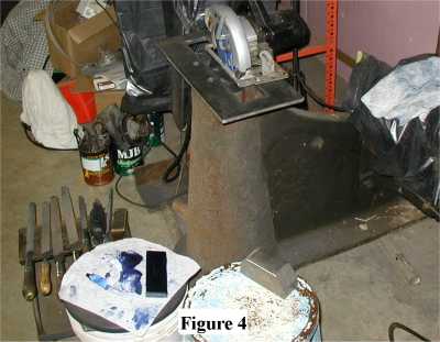
When I heard about Andrew's idea, I could see immediately that it would be really a really useful method for accomplishing this task. All I have
done is to make up a 1/2" thick plate, having a large slot (2 3/4" X 15 1/4") in its center. (See Figure 1).
This plate simply makes it easier to keep the Skil Saw on an even plane. It also allows for adding a temporary fence (if needed)to be used in
cleaning up the dovetails.
I made this plate to be used on both 25# and 50# Little Giants and for the Easy (one size fits all, I hope). It may fit other hammers in
that general range. It is 8 5/8" X 19 1/4", with three 3/8" diameter countersunk holes. It is attached temporarily to the top of the
frame's die cavity as follows:
Before you start any metal removal, it's a good idea to level the whole frame as accurately as possible. This makes it easier
to check progress with a simple level. You can do this right away, or you can wait until you have trued up the top surface of the
hammer's frame as discussed next.
Note on choosing a reference surface:
The horizontal frame surface that has the die cavity on most Mayer Bros. hammers has been planed flat and can be used as the
reference surface for cleaning up the die cavity. However, occasionally, as I just discovered from another blacksmith,
sometimes that top surface has been left "as cast" and the parting line is still there. The bottom of the die cavity was,
of course, planed to be true during manufacture. If the reason for your messed up die cavity is that the hammer had
a short die in it, that has beaten down the center of the cavity, then the outer edges may still be okay.
If so, you can use those "good" areas as the reference to level the fixture that the skil saw will ride on.
You can either grind the top surface to be parallel with the "good" parts of the die cavity or you can shim the fixture to level it.
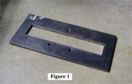
-The planed horizontal surface of the hammer frame is first trued up to within a few thousandths of truly flat by spotting it with
a flat plate coated with hi-spot compound, then filing off the high spots. (See Figure 2)
See the text below (Part C) for more information on how this "flattening" process is performed.
-The slotted plate is then located as squarely with the die cavity as possible and the hole locations are transfer punched into the
frame. Next, Drill 5/16" holes about 1" deep and tap 3/8-16.
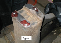
-Attach the plate with three 3/8-16 by 3/4' countersunk bolts, double check "level" and alignment with the die
cavity. (See Figure 3). Even if you did level the frame, you may want to recheck now.
If your hammer has a nice flat surface for the saw to ride on, and you feel comfortable with handling the saw in this mode,
you probably don't even need this plate. But if the surface in question is chewed up, or if you are concerned about being able to hold
the saw steady, I will loan this plate out to anyone who will come and get it and return it to me in a reasonable length of time. I also have
a drawing of the plate, if you want that.
Part C:
Pete's modified method of "scraping in" the die cavity.
I say "modified" because the method I am about to describe isn't REALLY scraping at all, since I don't use scrapers. If you already understand
scraping, you don't need to read any further and you probably would be appalled if you did.
Materials needed:
-2 "Flats" plates that are about a quarter of an inch narrower than the die cavity and a couple of inches longer. They should be about 1/2" thick.
They should be flat and parallel, both sides to about +/- a couple of thousandths.
-1 "Flat" plate that is about as long as the die cavity is and about as wide as the dovetail is. This plate should be only about 1/4" thick.
-Hi Spot Blue. You can get little tubes of it from MSC. I have read that some people use Prussian Blue Oil Paint in a tube (artists supply house).
-A couple of double cut or smooth files that are about 10 inches long.
-A 7 1/4" Skil Saw--- or a smaller saw and matching abrasive blade.
-A 7" diameter abrasive wheel such as those used by us Midwesterners to cut roofing steel.
-A 4 1/2" angle grinder with abrasive wheel.
-A Dremel tool and several abrasive bits that are about 1" long and tapered from about 1/4" at the base to a point at the end.
-A couple of pairs of "Refinishing gloves". This bluing gets all over everything. It takes several days to get it off your hands.
Optional:
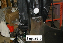
I made a plate to hold an in-line dial indicator. (See Figure 5). This gage-holding plate slides over the big plate, with
the foot of the dial indicator sensing the height of the floor of the die cavity. This way you can check your progress more accurately than with a level.
It is probably overkill.
The Actual "Scraping" process: (For the Floor of the die cavity)
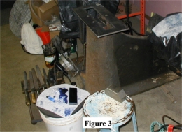
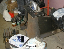
1. Use the abrasive wheel in the Skil Saw as described in Part A, above to rough the bottom of the cavity down to the approximate final level. I blocked
the guard open. You need to take safety into your own hands on this one. (See Figure 4).
You may want to skip this part of the process if your die cavity isn't chewed up much. If you have less than 15 or 20 thousandths to remove,
go to step 2.
On the two hammers that I did using this process, I had to remove almost a 1/4" of material and the dovetails were badly chewed up, too. I simply
set the saw blade down enough to cut, then slid it back and forth on the plate, indexing the saw from side to side a little with each pass. I set up a
simple fence to limit the side movement of the saw.
When I did this, I was surprised at how fast the abrasive wheel cuts the cast iron. It is easy to go overboard, so take it easy. Don't expect
perfection of the surface with this step. I'll bet I had some 5 or so thousandths grooves left when I finally went to the "scraping".
2. Once you have the floor of the die cavity pretty well cleaned up, and wiped clean, apply a dab of bluing to one of the two "Flats". Rub the
other flat against it to evenly distribute the bluing to a very thin coating.
2.1 Then carefully lower either one of the flats, blued side down, onto the freshly ground and cleaned surface and rub it around gently. Carefully
remove the plate. Look for blue spots which are the highest spots on that surface.
If this is your first time to do this, I suggest using the Dremel tool to GENTLY grind away all of the blue. Don't try to dig in, just get rid
of the blue.
If you are somewhat experienced at this and you can see from this first bluing where you have big areas to adjust, you can use an angle grinder
or even the skil saw.
Now take the 10" file in hand and file across the whole surface. A dozen strokes or so should do it.
This step will sort of average out the high spots and blend the area that you just hit with the Dremel tool.
3. Steps 2 and 2.1 comprise one "cycle" of bluing, scraping and filing. Continue to make these "cycles" until the bluing covers about 80 percent
of the whole floor of the die cavity. Every few cycles, check the level-ness of the cavity both ways to make sure you are producing not only a
FLAT surface, but one that is parallel to the machined flat surface of the frame that we are referencing to. If you find (and you probably will)
that the surface isn't perfectly level with the reference plane ("level" both ways within a sixteenth of a bubble or better), Then estimate the
amount of material that you need to remove from the HIGH side. You can use shim stock on the low side to help in this.
Then, grind out that much from about a 1/2" square area on the high side. This will be a temporary reference area.
Now, blue up again and rub. You will notice that there's no blue on the "temporary reference area" that you just ground. Good. Now, grind away
the blue from the rest of the high end but don't remove any blue from the low third or so of the cavity. Make additional cycles until blue starts
to show up on that high side temporary reference area. Now you have approximately corrected for "out of level".
Continue making cycles until you see bluing on at least 80 percent of the floor of the cavity. Make one final filing pass and you are done.
Note 1: You don't have to put a new dab of bluing on the Flats every time you perform a cycle, but you do need to rub the two flats together each
time to re-distribute the existing bluing. I probably add bluing every 3 or 4 cycles. The trade-off is that each time you test the surface (rub the
flat on the surface) without re-bluing, you are getting a thinner and thinner layer of blue onto the working flat.
Note 2: When I do this, I use the dial indicator approach. This makes it easy to keep things level, so I don't have major corrections to make later.
I figure that if I get the surface flat to within +/- 3 thousandths, that is plenty good enough.
Once the floor of the die cavity is clean and flat, you will have to cut a plate to fit the space that you ground away. You need to get the
floor close to the original depth, but only within an eighth of an inch or so, with too high being better than too low. The problem is that the
lower die overhangs the dovetails a little. If the die sits too low in the cavity, the upper portion will hit the dovetail. The plate does not
need to be fastened in place. If this floor plate seems to wiggle a little, locate the offending high spot on the plate and "scrape" it away.
You may have to adjust the width of the plate a little to make up for any lack of ability of getting to the very edges of the floor where it
intersects the dovetails. I don't see this as a problem as long as the plate is as wide as the bottom of the die.
"Scraping" the Dovetails:
The dovetails on the two hammers that I did were in real bad shape when I started. In both hammers, one dovetail was so bad that you couldn't
tell there was any angle to it at all! I am not going to go into any detail at all about fitting die keys, since this was covered well by
Sid Suedmeier in an article he wrote a few years ago.
But, what I WILL cover is how I used the above "scraping" technique to clean up those dovetails.
The general idea here is to use a 10 degree angle "standard" or a new die as the reference for rebuilding the dovetails. For this article,
I will use a new die.
It really doesn't matter even if the new die doesn't have exactly 10 degree dovetails, because we will fit the hammer to the die, so-to-speak.
So, once a new plate has been fitted to the newly leveled floor of the cavity, you simply blue the die on one dovetail surface and then rub it on
the adjoining die cavity dovetail to determine where to start.
I suggest you start by fixing the front dovetail first. This is the surface where you will add a single shim when you finally install the die.
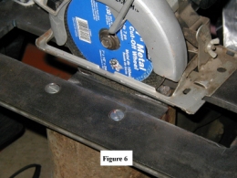
To get started, do a rough bluing and sighting job to see how much work you have to do. If there's a long way to go, you can take some of it out with
the angle grinder, then set the Skil Saw to 10 or 12 degrees and use the side of the blade to clean up the angle grinder mess.
(See Figure 6). The reason I say "10 OR 12 degrees" is that the blade deflects a little when you push sideways,
so you may need to compensate a little.
Use the grind-file-blue-test process described above to get about 80 percent or more contact between the die and the frame dovetails. You will
need to use the thinner, smaller "flat" from time to time since the die usually isn't as long as the cavity. Make sure that you keep the base
of the die flat against floor of the die cavity as you test.
Do the same thing with the back side of the die cavity. Read the Sid Suedmeier article on fitting die keys before you do this side, since this
is the side where the die key will go.
It's at this point that you need to find out which way the die is tapered and which way the dovetail is tapered. And, since you are probably going
to do major work in this area anyway, this is the time to make any necessary major adjustments. The "Sid" article will be of much value in this area.
Note 3: You can apply all of these PRINCIPLES to the upper die cavity, too. In my short experience, the hammer heads (rams), which are made
of cast steel don't get chewed up as badly as the die cavities in the cast iron frames do.
Note 4: Die keys can be made or purchased. No matter where they come from, they will have to be fitted, using a process similar to what you
have seen above. (See the "Sid" article again!)
Note 5: A 1/8" per foot taper equals about 0.6 degrees. A 1/4" per foot taper equals about 1.2 degrees.
Note 6: Here is a recent article about I wrote about die tapers. It also tells you where to find the very important "Sid" article.
Die Key Taper Information For Mayer Bros. Triphammers
By Pete Stanaitis
Little Giant die cavity shapes have always been a mystery to me. Sid gave me this information about lower die cavities to help dispel
some of my lack of knowledge this summer at LaCrosse. I meant to write a short article around it and to submit it to the Metalsmith sooner, but
haven't gotten around to it till now:
Bottom Die Cavity Only:
Sid says:
"NO Sowblock" means that there is No Longitudinal taper in the dovetail. The dies should have a 1/8" per foot taper. So this means that the
die key needs to have a taper of 1/8" per foot.
"WITH Sowblock" means that the sowblock itself has a Longitudinal taper of 1/8" per foot in the die dovetail. The die should have a taper
of 1/8" per foot also. So this means that the die key needs to have a taper of 1/4" per foot.
Sid (now Roger Rice) sells different die keys to make up for these differences. They are cut to approximate tapers. The tapers in the machines themselves
may vary a little depending on what has been done to them throughout their lives.
You will always have to fit a new key.
The "Sid" Die Key fitting article
Sid published a 3 page article on die key fitting in the May-June, 1994 issue of the BAM newsletter and it was re-published soon after in The
Metalsmith.
That article and more about dies now resides on the Little Giant website. Go to this page for lots of useful information: :
Little Giant Hammer Die Key Fitting Article
There's the story. I hope I haven't bored you to death, but I see this as a set of work instructions, not a newsy article. Please email me
with details if you see something in here that is unclear or misleading.