-My Frequency Counter for 30kHz to 150kHz ZVS Induction Heaters.
---------------OR:-------------
-Three Cheap Frequency Counters: Which One Works Correctly for my Application?
Created: July 7, 2019
Last Revised: October 20, 2023
Home
ZVS 1000 Watt Induction Heater Page
1800-2500 Watt ZVS Induction Heater Page
Work Coils
Computing
Blacksmithing
Contact Us
Opening:
-Here's how I laboriously got through the process of getting a "cheap" frequency meter working properly,
to install on my Chinese 1000 Watt and 2500 Watt ZVS Induction Heaters.
It took me 4 different approaches before I got a working cheap frequency counter "system" that I could permanently attach to my induction heaters.
There are lots of frequency counters available. Cheap ones and expensive ones.
I wanted a cheap one that I could peramently attach to the heaters, not a Lab type for the bench.
On the internet there are many sources for kits, sources for preassembled units, and some of DIY projects.
This is the story of the four tries it took for me to get one that worked well:
This is a sad story with a good ending.
I have to admit that I made several errors along the way, so don't consider me the expert at this. I hope you can use this venture to avoid similar problems.
First Try:
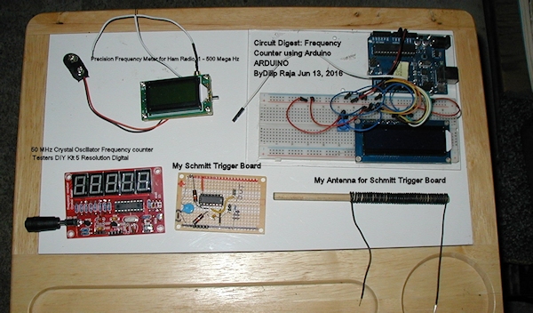
I saw a series of videos by Julian Illett, where he built a cheap (under USD $5.00) "50-MHz-Crystal-Oscillator-Frequency-counter-Testers-DIY-Kit-5-Resolution-Digital" from a kit.
https://www.ebay.com/itm/50-MHzC1Hz - 50 MHz Crystal Oscillator-Frequency-counter-tester
He didn't like it for the testing of crystals, but it seemed to be okay otherwise.
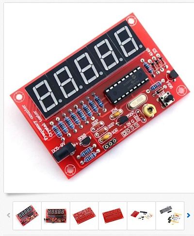
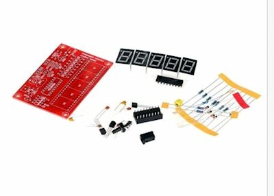
I bought one and built it.
Only then did I realize that needed a 5 volt square wave for an input.
I thought at the time that I could passively "steal" some of the 12 volt gate pretty square signal from the ZVS Induction heaters to feed it.
After several failed attempts and a blown Mosfet, I decided that was a bad idea. If I even lightly loaded the heater's gates, the passive
ciruits that I built caused the gate waveforms to round off too much, which, of course makes the Mosfets overheat and die.
Second Try:
So, I put that idea aside and went looking for an alternative that wouldn't connect directly to the circuit.
I found some cheap (USD $20- USD $30)frequency counters that radio guys use to measure transmitter outputs.
Those devices use a simple straight wire antenna to capture the signal. I bought one of those, already assembled:
https://www.amaz1 MEGA Hertz to 500 MEGA Hertz Frequency Meter
The ad said "Precision Frequency Meter for Ham Radio, 1 - 500 Mega Hz".
After I got it I found that it wouldn't measure down to the range that I need. The "1" meant One MegaHertz, not "1 Hz" as I had thought!!!
Third Try:
Next, I found an Arduino based frequency counter "instructable".
Of course that one also required a square wave input. I built it anyway. (Don't ask me why!)
At that point, I went looking for front end circuits, such as those that would be used in oscilloscopes and more expensive frequency counters.
Not as easy a task as I thought it would be. But I finally rediscovered Schmitt triggers.
So now I knew how I could produce a square wave for the input of any PIC based frequency counter.
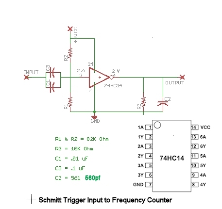
And I did have some Hex inverting Schmitt trigger chips handy so I thought I'd go that way.
Then, of course, I had to deal with conditioning the input of the schmitt trigger circuit without loading down the signal's source
or blowing up the Schmitt trigger's input circuit.
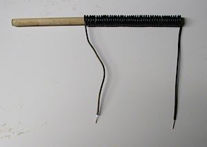
For a signal source, I made a 44 turn "antenna" coil wound on a 1/4" wooden dowel and located it in close proximity to the induction heater's
work coil to capture the signal.
This Schmitt Trigger circuit works well with a peak to peak sine wave of 1.5 volts (or more) and might even work with a bit less.
I haven't tested it yet with distorted or noisy signals, but the data sheets say that it ought to work with a wide range of signals.
Here's the schematic diamgram of the ciruuit that I am using. As you see, I am only using one of the six hex Schmitt inverters on the chip, but they only cost about USD$1.00 each
However!!!, Once I got the "instructable" Arduino counter running, I discovered that it was a really poor attempt at a frequency counter.
Its resolution was very poor at the frequencies that I needed to measure.
For example, At 100 Kilohertz, the minimum difference it can resolve is 11.1 kilohertz!
No good at all for me, since I need a resolution of 100 Hz or even less.
Fourth Try- Success, Finally!:
By this time, I finally realized that my original cheap kit was the way to go, but it needed the Schmitt Trigger Signal Conditioning circuit that
I had built for my "Third Try".
As you have already seen, here are the 3 components of the system that I ended up with:
-Antenna
-Signal conditioner
-The frequency Counter
You can see it in operation on several of my recent Induction heating Youtube videos at this playlist:
Some of Pete's Induction Heater Videos
Please, Please, Please contact me if you have anything to add or if you think I have missed something or I have gotten something wrong!!!