Current Transformer Sensor Circuit
Last Revised: October 19, 2023
Home
Computing
My Arduino Startup Page
Contact Us
I designed and built a simple circuit to test the idea of simply sensing when a power tool has been turned on.
A friend wants to be able to use some sort of signal to turn on his dust collector when ANY dust-creating machine in the shop is powered up.
He also wants the system to "know" which machine has been turned on so he can open and close the appropriate gate valves.
This system works well enough to light an LED when any device drawing more than about 150 watts is powered up when a "CT" (Current Transformer)
encircles two turns of one line wire.
In another application, a guy wants to develop a system to detect if and when a device that is under power draws too much current so he can
automatically do something about it.
The device you will see here can handle both of these tasks.

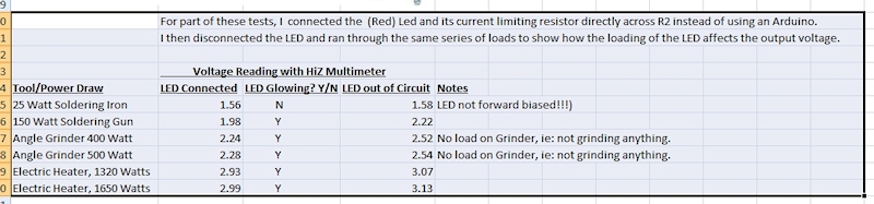
The testing below shows how much the CT Sensor Circuit output varies with changes in current flow, from a practical standpoint.
I have been using 2 turns of one AC power line lead through the CT for these tests. Obviously, one turn would yield half these numbers,
and 3 turns would yield half again as much output. But I wanted an output range that would fit the zero to 5 volt limits for an Arduino.
 <
<
Here you can see the complete test setup. Note the AC plug/receptacle setup. It uses 3 separate wires so it is easy to clamp the CT
around either the hot or the neutral.
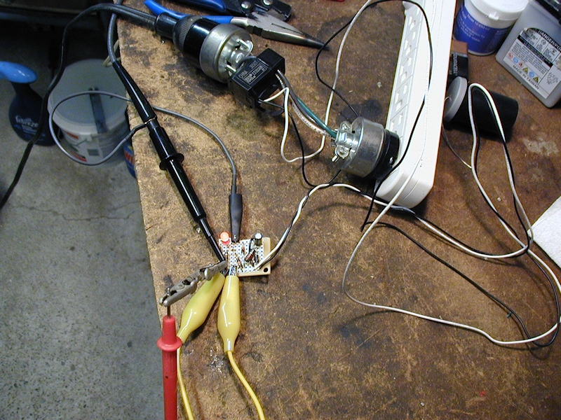
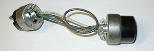
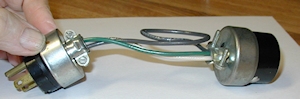
See how the adapter is made. By making the black wire long enough for a loop, we have an easy choice of either one or two turns within the CT:
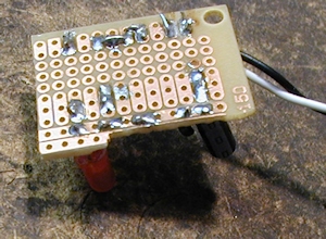
Here are top and bottom views of the simple circuit board:
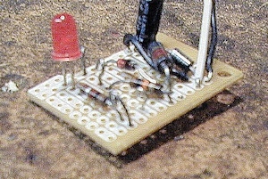
If you look carefully at the top view of the board, you can see a few test points sticking up. They made it easy for me to connect and/or disconnect the
LED from the circuit. Those points are labeled on the schematic.
Hmmm---- I just noticed that I actually used a 100 ohm resistor in series with the LED, even though the schematic says 220. It'll work either way, of
course. It's just that, with 220 ohms, the LED might not light up with the 150 watt soldering gun.
A Prototype Packaging Job
So you can see that we already have a workable "Power On" digitizer using a current transformer and a little circuit board.
But the user had to make up the 6 inch long "extension cord" (the AC plug/receptacle setup) that separated the neutral and hot wires
so the CT could be clamped to one of them. And that assembly would be seen hanging out of the wall. Works, but maybe not pretty enough?
Well, I thought about it and then made up a prototype for a packaged gadget that simply plugs into the wall, presenting a 120 volt
15 amp receptacle for the user's machine.
And, of course, a pair of small digital output leads to connect to an Arduino.
To make it easy to do, as a "one off", I bought the cheapest "Smart Outlet" that I could find at Walmart and severely modified it for that service.
I really had to work at it to shoehorn all the parts into it. (And to get all the unneeded parts out, while preserving the plug/receptacle components).
I am not suggesting that you do the same unless you really know what you are doing from the safety viewpoint!
I hope these three pictures explain what I had in mind:
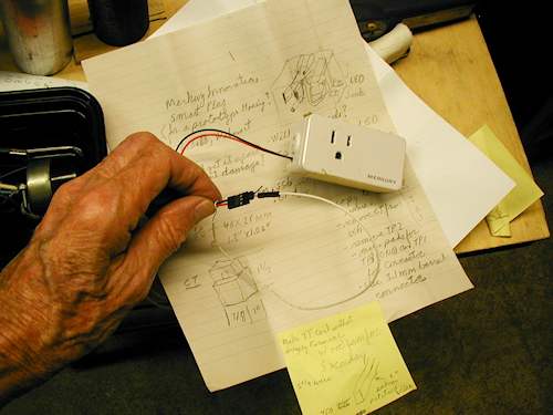
The nice thing about using this exact shape of Smart Plug is that it already has a pretty beefy built-in plug and receptacle setup.
If you were to 3D print a case of your own, you would need to give that a serious consideration.
Also, this particular case design does not cover up the second receptacle of a normal duplex receptacle.
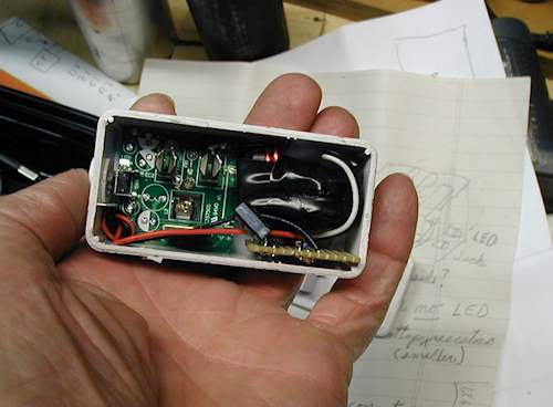
Here you can see how I stuffed the CT and my little pcboard into the right hand side of the case.
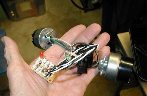
Just a reminder as to what the little PCboard looks like out in the open.
Well, that's it for now. Feel free to ask questions, or to criticize.