My Arduino Page
Last Revised: December 19, 2024
Home
Computing
My Arduino Startup Page
Contact Us
Here I want to show some of my progress with arduino, give credit to Jermey Blum and to the folks at Adafruit, and to show why I chose Jeremy Blum's recent book
"Exploring Arduino" to further my capabilities.
I won't take you through a whole construction project. Rather it'll simply show the projects I have done recently and give
a SHORT explanation each of them, explaining what I learned from them.
Here's my first project, a datalogger for my woodgas-to-electric project:
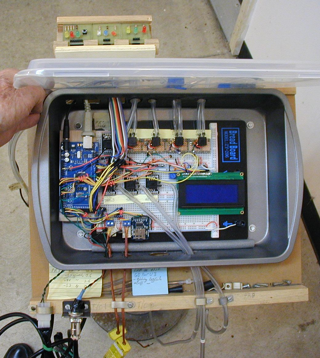
It measures,records and displays (on the LCD Screen) 3 temperatures, 8 pressures, on-time, engine throttle position,
and engine oxygen sensor output. It records a "Marker Button" and provides a "traffic lights" visual display for 2 of the most important operating variables.
(About 1000 lines of code).
Updated Datalogger for Woodgas
I built and integrated that device into my woodgas system over a one year plus period, but now I need to learn more about using all that data to
actually do things TO the equipment that I am monitoring and how to take advantage of some of the more complex commands, sensors and output devices
that are available. By that I mean: I want to learn more about commands that I haven't had to use yet, sensors that do things I haven't tried and
about output devices in general.
So when Jeremy Blum's new book, Exploring Arduino became available, I bought a copy, read it from cover to cover a couple of times, then selected the
5 projects that I thought would best enchance my knowledge for now.
And here they are:
Speaker, Ch9:
Digital Potentiometers
SPI bus
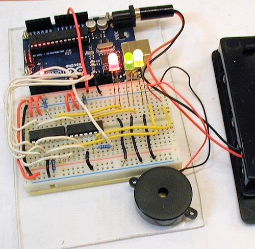
Since the neither the Arduino UNO or the Mega2560 have analog OUTPUTS, I wanted to learn how analog outputs could be produces.
The digital potentiometer is one answer.
The output of the 3 LEDS is being varied via analog voltage changes by 3 of the 4 digital potentiometers (2 per chip)
that are on the breadboard, not by pwm. While the circuit and the software make the light output vary, "tone" is operating
in the background to drive the speaker's frequency, but the 4th digital pot is making the speaker's volume rise and fall.
Bargraph, Ch 7:
Shift Registers
Distance Sensors
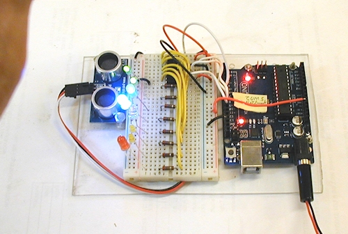
Each shift register effectively adds 8 output pins to an Arduino (minus the one it is connected to). Here, One Arduino pin drives
8 LEDs in this example. In the book's project, a Sharp IR distance sensor is used to turn distance to an object into a bar graph.
The Sharp IR distance sensor sends an analog output to the program, but I didn't have one. So I converted the code to use a Parallax
Ping Sensor (Sonar sensor) to work instead. It actually reports the time (in microseconds) that it takes for a "ping" to go out,
hit something, and to return, so one has to calculate the distance from that info. This was a good exercise for me.
Ch4:
H-Bridge DC motor control
Separate power supply
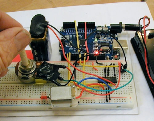
A DC motor is likely to draw more current than the ARduino can supply, so a separate 9 volt battery is used for demonstration purposes.
The H-Bridge is capable of driving motors in both directions and at varying speeds.
A potentiometer is used to tell the H bridge what to do.
The potentiometer, when roughly in the center position, tells the motor to stop
When it is turned ccw, the motor turns in one direction, faster as the pot is turned farther. when the pot is
turned cw from the center, the motor goes faster and faster in the other direction. The idea here is that the small signal current to
the H-Bridge controls a large current to the motor, including directional control.
Sweep, Ch4:
RC Servo
Separate Power Supply (9 volt battery in this case)
Linear power regulator
IR Distance sensor
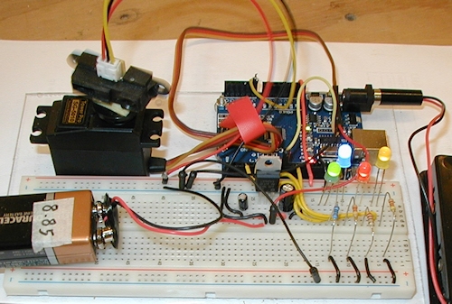
Since the servo draws more power than it can get from the Arduino, it needs a separate power supply, hence the 9 volt battery,
But the servo wants only 5 volts, so this circuit includes a linear power regulator to reduce the battery' 9 volt output to 5 volts.
The IR sensor is glued to the servo. The servo is programmed to sweep to 4 positions in an arc a little shorter than 180 degrees.
It stops momentarily at each position while the distance sensor reads the distance. That distance is converted to an appropriate pwm
output proportional to the distance seen by the sensor at that position. The pwm signal illuminates an LED in proportion to the distance,
closer equals brighter. Then it moves to the next position, and so on, finally resetting and doing it all over again.
The project called for all blue LEDs But I used LEDs of differing colors here, and learned how much the light output varies from one color
of LED to another. I had to make large changes in series resistance values to make them more or less equal brightness for a given pwm percentage.
Fun with sound, Ch12:
Timers
Interrupt
Schmitt Trigger

Some day I want to work on an ignition controller for a certain old ATV machine, so I know I will need to understand interrupts to control
the ignition event timing. And timers need to be used with interrupts, since you can't use the "delay" command while an interrupt is running.
So this simple looking project actually has a lot going on. It is using the "tone" library to create a set of ever increasing frequency
tone bursts. But one can use a button press to move the base frequency up one notch whenever one wants, without have to wait for
the Arduino's IDE "loop" to cycle back to the button press event in the code. This is done with the Schmitt Trigger debounced button
and and an interrupt.
Using an Arduino as an Engine Control Unit
For a many months now, I have been attempting to make a replacement for the old points and condensor system that makes the sparks on older engines.
I know that there are many simple, cheap "solid state" replacements out there, but they don't have the adjustable and/or programmable spark advance
capabilities that I want. Older Onan 2 cylinder generator sets and old Cushman Tracksters are two of my target vehicles.
The first thing I wanted to do was to get rid of the high voltage wiring so I tried out a COP (Coil-On-Plug) pack like those used in most modern gasoline powered
vehicles.
First, I wanted to see if an Arduino could directly trigger a COP pack. Well, it does work.
See:
Arduino Triggering Coil On Plug Pack
Then I built an engine rotation simulator using magnets in a rotor attached to a small DC motor powered by an arduino, using one of the H-Bridge experiments
that I had made earlier. Using another Arduino and a Hall Effect sensor, I made up a device to read the rotor magnets and to display rpms to the serial monitor.
I expanded my Arduino COP driver by adding a potentiometer so I could make sparks at varying rates.
Arduino COP and Hall Effect Engine Simulator
The next step was to connect it all together so my engine simulator rotor would directly trigger the COP pack. At this time I also added and LCD display
so I could see what's going on. This allowed me to eliminate one of the Arduinos in my test setup.
By that time, I had also learned that I needed to be able to adjust the "dwell time" of the COP pack to determine the best trigger pulse length so that
change is also documented here:
Integrating COP Driver and Engine Simulator with Adjustable Dwell Time
Now, with the confidence that the thing was actually working, I decided to add more "poles" to my magnetic rotor.
In usual automotive practice, they sense the presence of gear teeth on a wheel to determine engine speed. In order to determine where the crankshaft is
in relation to the gear teeth, they usually have one missing tooth in the gear to identify the Top Dead Center point of the crankshaft for the number one cylinder.
Since this "missing" tooth isn't really there, they have to calculate its location. Then they use that estimate of where the missing tooth should be to calulate
spark and fuel injector timing.
I didn't want to have to "guess" where the missing tooth should be, so I wanted to experiment with an interesting feature of Hall Effect sensors.
You can see this experiment at:
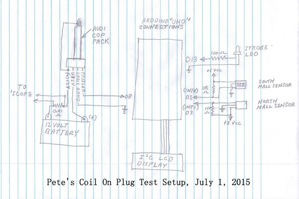
Adding 4 pole rotor with 2 Hall Effect Sensors
Here's a simplified schematic of my July 2, 2015 test setup:
Ignition Timing Drift Issues finally solved, January, 23, 2016
Timing Drift with my Uno Ignition controller has been a huge problem. No matter what I did, for the longest time,
I could not keep the system from losing about 8 degrees between about 300 and 3000 rpms. I have finally solved
the problem and that's what this update is about.
Drift Improvement Video
January, 2016 Code for My Arduino Ignition Controller
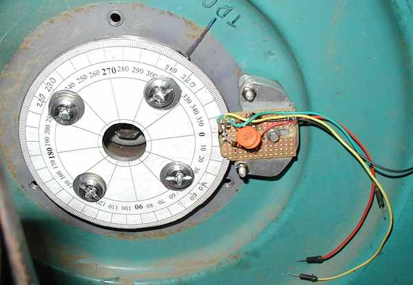
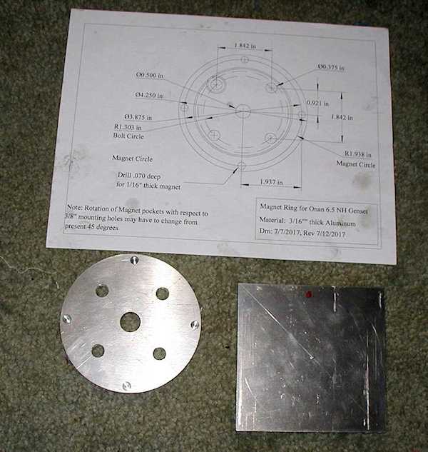
November 17, 2017:
I have been working on this project, on and off. It has now advanced almost to an operating system. I am now using a two tower CNP pak to
run an Onan 2 cylinder generator set. It is still in test mode.
Here are two pictures of the magnet wheel that I am currently using on an Onan 6.5NH Generator Set:
You can see my progress here:
My Youtube Ignition Controller Playlist
December 19, 2024:
My solutions to enclosing some of my projects that need easily visible displays.
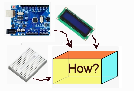
Click Here for my Arduino Enclosure Video
More to come as I learn more.